Toyota Tacoma (2015-2018) Service Manual: Four Wheel Drive (4WD) Low Switch Circuit Range / Performance (P2772)
DESCRIPTION
This DTC is output when a malfunction in the L4 detection switch is detected.
|
DTC No. |
Detection Item |
DTC Detection Condition |
Trouble Area |
|---|---|---|---|
|
P2772 |
Four Wheel Drive (4WD) Low Switch Circuit Range / Performance |
|
|
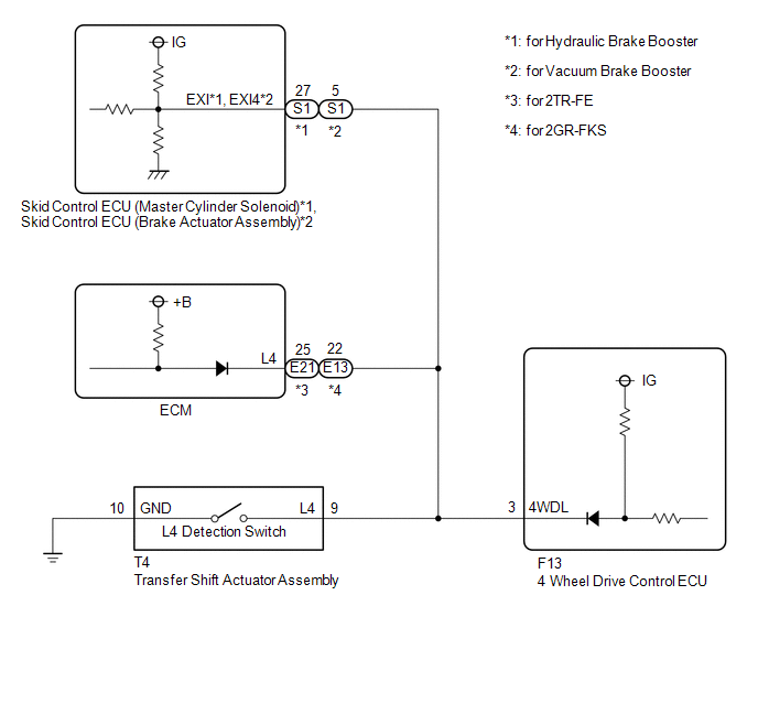
WIRING DIAGRAM
PROCEDURE
|
1. |
CHECK HARNESS AND CONNECTOR (4 WHEEL DRIVE CONTROL ECU - TRANSFER SHIFT ACTUATOR ASSEMBLY) |
(a) Disconnect the F13 4 wheel drive control ECU connector.
(b) Disconnect the T4 transfer shift actuator assembly connector.
(c) for Hydraulic Brake Booster:
Disconnect the S1 skid control ECU (Master Cylinder Solenoid) connector.
for Vacuum Brake Booster:
Disconnect the S1 skid control ECU (brake actuator assembly) connector.
(d) for 2TR-FE:
Disconnect the E21 ECM connector.
for 2GR-FKS:
Disconnect the E13 ECM connector.
(e) Measure the resistance according to the value(s) in the table below.
Standard Resistance:
|
Tester Connection |
Condition |
Specified Condition |
|---|---|---|
|
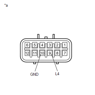
F13-3 (4WDL) - T4-9 (L4) |
Always |
Below 1 Ω |
|
T4-10 (GND) - Body ground |
Always |
Below 1 Ω |
|
F13-3 (4WDL) or T4-9 (L4) - Body ground |
Always |
10 kΩ or higher |
| NG | .gif) |
REPAIR OR REPLACE HARNESS OR CONNECTOR |
|
.gif)
|
2. |
CHECK TRANSFER SHIFT ACTUATOR ASSEMBLY |
(a) Turn the ignition switch to ON.
(b) Turn the transfer position switch to L4.
(c) Turn the ignition switch off.
(d) Disconnect the T4 transfer shift actuator assembly connector.
|
(e) Measure the resistance according to the value(s) in the table below. Standard Resistance:
|
|
| OK | |
REPLACE 4 WHEEL DRIVE CONTROL ECU |
| NG | |
REPLACE TRANSFER SHIFT ACTUATOR ASSEMBLY |
 Front Differential Oil Temperature Sensor Circuit High (P17C8)
DESCRIPTION
This DTC is output when a short to B+ or open circuit in the oil temperature
sensor is detected.
DTC No.
Detection Item
DTC Detection Condition
...
 Invalid Data Received From Vehicle Dynamics Control Module (U0416)
DESCRIPTION
This DTC is detected if a wheel speed malfunction signal is sent from the skid
control ECU (brake actuator assembly).
DTC No.
Detection Item
DTC Detect ...
Other materials:
Terminals Of Ecu
TERMINALS OF ECU
1. AIR CONDITIONING AMPLIFIER ASSEMBLY
HINT:
Check from the rear of the connector while it is connected to the air conditioning
amplifier assembly.
Terminal No.
(Symbol)
Wiring Color
Terminal Description
Condition
Spe ...
System Description
SYSTEM DESCRIPTION
1. SYSTEM DESCRIPTION
(a) The Electronic Controlled Automatic Transmission (ECT) is an automatic transmission
that has its shift timing electronically controlled by the ECM. The ECM detects
electrical signals that indicate engine and driving conditions, and controls the
sh ...
Front Speed Sensor RH Performance (C1409,C1410)
DESCRIPTION
Refer to DTCs C1401 and C1402 (See page ).
DTC Code
DTC Detection Condition
Trouble Area
C1409
C1410
One of the following conditions is met:
When the vehicle is driven in reverse at a speed of 3 km/h (2
...
