Toyota Tacoma (2015-2018) Service Manual: Front Differential Oil Temperature Sensor Circuit High (P17C8)
DESCRIPTION
This DTC is output when a short to B+ or open circuit in the oil temperature sensor is detected.
|
DTC No. |
Detection Item |
DTC Detection Condition |
Trouble Area |
|---|---|---|---|
|
P17C8 |
Front Differential Oil Temperature Sensor Circuit High |
|
|
WIRING DIAGRAM
Refer to DTC P17C7 (See page .gif) ).
).
PROCEDURE
|
1. |
CHECK OIL TEMPERATURE SENSOR |
(a) Disconnect the 4 wheel drive control ECU connector.
|
(b) Measure the resistance according to the value(s) in the table below. Standard Resistance:
|
|
(c) Measure the voltage according to the value(s) in the table below.
Standard Voltage:
|
Tester Connection |
Switch Condition |
Specified Condition |
|---|---|---|
|
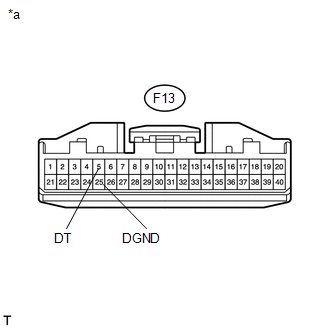
F13-5 (DT) or F13-25 (DGND) - Body ground |
Ignition switch ON |
Below 1 V |
|
*a |
Front view of wire harness connector (to 4 Wheel Drive Control ECU) |
| OK | .gif) |
REPLACE 4 WHEEL DRIVE CONTROL ECU |
|
.gif)
|
2. |
CHECK HARNESS AND CONNECTOR (4 WHEEL DRIVE CONTROL ECU - OIL TEMPERATURE SENSOR) |
(a) Disconnect the F13 4 wheel drive control ECU connector.
(b) Disconnect the F38 oil temperature sensor connector.
(c) Measure the resistance according to the value(s) in the table below.
Standard Resistance:
|
Tester Connection |
Condition |
Specified Condition |
|---|---|---|
|
F13-5 (DT) - F38-1 (DT) |
Always |
Below 1 Ω |
|
F13-25 (DGND) - F38-2 (DGND) |
Always |
Below 1 Ω |
(d) Measure the voltage according to the value(s) in the table below.
Standard Voltage:
|
Tester Connection |
Switch Condition |
Specified Condition |
|---|---|---|
|
F13-5 (DT) or F38-1 (DT) - Body ground |
Ignition switch ON |
Below 1 V |
|
F13-25 (DGND) or F38-2 (DGND) - Body ground |
Ignition switch ON |
Below 1 V |
| OK | |
REPLACE OIL TEMPERATURE SENSOR |
| NG | |
REPAIR OR REPLACE HARNESS OR CONNECTOR |
 Front Differential Oil Temperature Sensor Circuit Low (P17C7)
DESCRIPTION
This DTC is output when a short to ground in the oil temperature sensor is detected.
DTC No.
Detection Item
DTC Detection Condition
Trouble Ar ...
 Four Wheel Drive (4WD) Low Switch Circuit Range / Performance (P2772)
DESCRIPTION
This DTC is output when a malfunction in the L4 detection switch is detected.
DTC No.
Detection Item
DTC Detection Condition
Trouble Area
...
Other materials:
Clutch Switch Circuit
DESCRIPTION
Clutch switch circuit inspection is necessary for manual transmission vehicles.
When the clutch pedal is released, the ECM receives the positive (+) battery
voltage through the ECU-IG NO. 2 fuse and ignition switch. While the clutch pedal
is depressed, the clutch switch assembly se ...
Replacement
REPLACEMENT
PROCEDURE
1. RECOVER REFRIGERANT FROM REFRIGERATION SYSTEM
(a) Start the engine.
(b) Operate the cooler compressor under the conditions shown below:
Item
Condition
Engine Speed
Idling
Operating Time
3 minu ...
System Diagram
SYSTEM DIAGRAM
Transmitting ECU (Transmitter)
Receiving ECU
Signal
Communication Method
4 wheel drive control ECU
Skid control ECU (Brake actuator assembly)
High-Low actuator fail
4WD status ...
