Toyota Tacoma (2015-2018) Service Manual: Engine Oil Cooler
Components
COMPONENTS
ILLUSTRATION
ILLUSTRATION
ILLUSTRATION
Inspection
INSPECTION
PROCEDURE
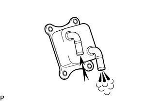
1. INSPECT OIL COOLER ASSEMBLY
|
(a) Check the oil cooler assembly for damage and clogging. If necessary, replace the oil cooler assembly. |
|
Installation
INSTALLATION
PROCEDURE
1. INSTALL OIL COOLER ASSEMBLY
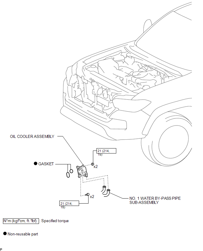
(a) Install 2 new gaskets to the oil bracket sub-assembly.
(b) Install the oil cooler assembly with the 2 bolts and 2 nuts.
Torque:
21 N·m {214 kgf·cm, 15 ft·lbf}
2. CONNECT NO. 1 WATER BY-PASS PIPE SUB-ASSEMBLY
(a) Connect the No. 1 water by-pass pipe sub-assembly.
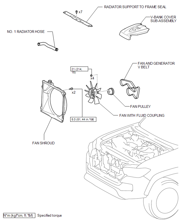
3. INSTALL FAN SHROUD
.gif)
4. INSTALL NO. 1 RADIATOR HOSE
5. INSTALL V-BANK COVER SUB-ASSEMBLY
6. ADD ENGINE OIL
7. CHECK ENGINE OIL LEVEL
8. ADD ENGINE COOLANT
9. INSPECT FOR ENGINE OIL LEAK
10. INSPECT FOR COOLANT LEAK
11. INSTALL RADIATOR SUPPORT TO FRAME SEAL
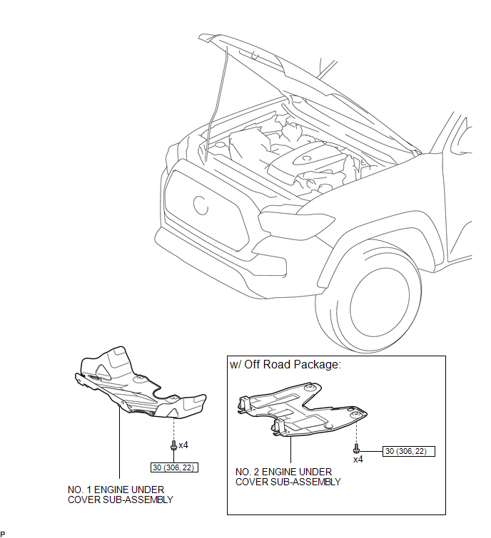
12. INSTALL NO. 1 ENGINE UNDER COVER SUB-ASSEMBLY
13. INSTALL NO. 2 ENGINE UNDER COVER SUB-ASSEMBLY (w/ Off Road Package)
Removal
REMOVAL
PROCEDURE
1. REMOVE NO. 2 ENGINE UNDER COVER SUB-ASSEMBLY (w/ Off Road Package)
2. REMOVE NO. 1 ENGINE UNDER COVER SUB-ASSEMBLY
3. REMOVE RADIATOR SUPPORT TO FRAME SEAL
.gif)
4. DRAIN ENGINE COOLANT
5. DRAIN ENGINE OIL
6. REMOVE V-BANK COVER SUB-ASSEMBLY
7. REMOVE NO. 1 RADIATOR HOSE
8. REMOVE FAN SHROUD
9. DISCONNECT NO. 1 WATER BY-PASS PIPE SUB-ASSEMBLY
(a) Disconnect the No.1 water by-pass pipe sub-assembly.
10. REMOVE OIL COOLER ASSEMBLY
|
(a) Remove the 2 bolts, 2 nuts and oil cooler assembly. |
|
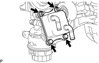
(b) Remove the 2 gaskets.

 Lubrication System
On-vehicle Inspection
ON-VEHICLE INSPECTION
PROCEDURE
1. INSPECT ENGINE OIL LEVEL
(a) Warm up the engine, and then stop the engine and wait for 5 minutes.
(b) Check that the engine oil level is ...
Other materials:
Disassembly
DISASSEMBLY
PROCEDURE
1. REMOVE RADIATOR DRAIN COCK PLUG
(a) Remove the radiator drain cock plug from the radiator assembly.
(b) Remove the O-ring from the radiator drain cock plug.
2. REMOVE RADIATOR TO SUPPORT SEAL
(a) Remove the 2 radiator to support seals from the radiator assem ...
Adjustment
ADJUSTMENT
CAUTION / NOTICE / HINT
NOTICE:
For vehicles equipped with VSC, if the wheel alignment has been adjusted, and
if suspension or underbody components have been removed/installed or replaced, be
sure to perform the following initialization procedure in order for the system to
functi ...
4WD Control Switch Circuit
WIRING DIAGRAM
PROCEDURE
1.
CONFIRM PROBLEM SYMPTOM
(a) Confirm the problem symptoms.
Result
Result
Proceed to
The 4WD indicator light (green) and 4LO indicator light remain off
A
The 4WD indica ...
