Toyota Tacoma (2015-2018) Service Manual: Disassembly
DISASSEMBLY
PROCEDURE
1. REMOVE FRONT BRAKE SHOE
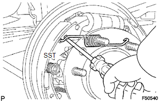
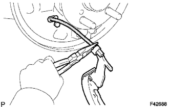
(a) Using SST, remove the shoe return spring from the front brake shoe.
SST: 09921-00010
|
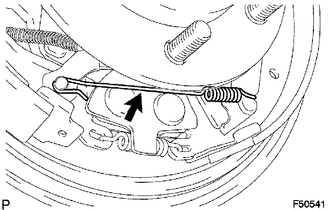
(b) Using needle-nose pliers, remove the return spring. |
|
|
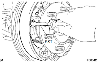
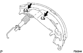
(c) Using SST, remove the shoe hold down spring cup, shoe hold down spring and pin. SST: 09718-00010 |
|
(d) Remove the parking brake shoe strut lower.
(e) Remove the tension spring and front brake shoe.
(f) Remove the automatic adjust lever spring and automatic adjust lever LH from the front brake shoe.
2. REMOVE REAR BRAKE SHOE
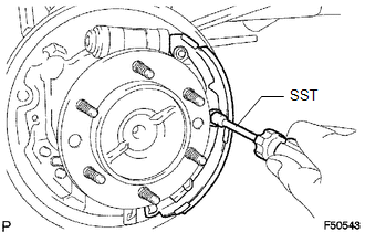
(a) Using SST, remove the shoe hold down spring cup, shoe hold down spring and pin.
SST: 09718-00010
|
(b) Using needle-nose pliers, disconnect the parking brake cable No. 3 and remove the rear brake shoe. |
|
|
(c) Using a screwdriver, remove the 2 C-washers, parking brake shoe lever, parking brake reaction lever and parking brake shoe strut set. |
|
3. REMOVE FRONT OR UPPER REAR WHEEL BRAKE CYLINDER ASSEMBLY
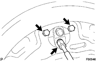
(a) Using a union nut wrench, disconnect the brake tube, and use a container to collect the brake fluid as it flows out.
(b) Remove the 2 bolts and rear wheel brake cylinder assembly.
4. REMOVE REAR WHEEL CYLINDER CUP KIT
(a) Remove the 2 wheel cylinder boots from the rear wheel brake cylinder.
(b) Remove the 2 pistons and compression spring.
(c) Remove the 2 cylinder cups from each piston.
(d) Remove the bleeder plug cap and bleeder plug from the rear wheel brake cylinder.
 Components
COMPONENTS
ILLUSTRATION
...
 Removal
REMOVAL
PROCEDURE
1. REMOVE REAR WHEEL
2. DRAIN BRAKE FLUID
HINT:
Immediately wash off any brake fluid that comes into contact with any painted
surfaces.
3. REMOVE REAR BRAKE DRUM SUB-ASSEMBLY ...
Other materials:
4WD ECU Malfunction (P163B)
DESCRIPTION
This DTC is output when a malfunction is detected in the 4 wheel drive control
ECU internal circuit.
DTC No.
Detection Item
DTC Detection Condition
Trouble Area
P163B
4WD ECU Malfunction
Dia ...
Removal
REMOVAL
PROCEDURE
1. REMOVE REAR SEAT CUSHION ASSEMBLY
2. REMOVE NO. 4 ROOM PARTITION COVER LH
3. REMOVE NO. 4 ROOM PARTITION COVER RH
4. REMOVE NO. 3 ROOM PARTITION COVER
5. REMOVE BACK PANEL GARNISH HOLE PLUG
6. REMOVE BACK PANEL TRIM
7. REMOVE FRONT DOOR SCUFF PLATE ...
Evaporator Temperature Sensor Circuit (B1413/13)
DESCRIPTION
The cooler thermistor sensor (evaporator temperature sensor) is installed on
the evaporator in the air conditioner unit to detect the temperature of the cooled
air that has passed through the evaporator and is used to control the air conditioning.
It sends signals to the air condi ...
