Toyota Tacoma (2015-2018) Service Manual: Components
COMPONENTS
ILLUSTRATION
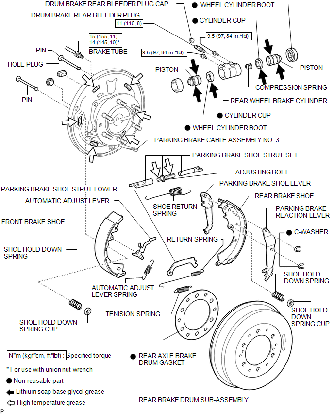
 Rear Brake
...
 Disassembly
DISASSEMBLY
PROCEDURE
1. REMOVE FRONT BRAKE SHOE
(a) Using SST, remove the shoe return spring from the front brake shoe.
SST: 09921-00010
(b) Using needle-nose pliers, remove the ret ...
Other materials:
Removal
REMOVAL
PROCEDURE
1. REMOVE WATER INLET WITH THERMOSTAT SUB-ASSEMBLY
(See page )
2. REMOVE NO. 1 RADIATOR HOSE
3. REMOVE NO. 2 RADIATOR HOSE
4. DISCONNECT RADIATOR RESERVE TANK HOSE
5. SEPARATE TRANSMISSION OIL COOLER HOSE (for Automatic Transmission)
(a) Disengage the c ...
Operation Check
OPERATION CHECK
1. CHECK WINDOW LOCK FUNCTION
(a) Turn the ignition switch ON.
(b) Press the window lock switch of the power window regulator master switch
assembly.
HINT:
The illumination (LED) built into the switch knob of each seat does not turn
off.
(c) Check that the power window fo ...
Confirm Cellular Phone Functionality
PROCEDURE
1.
CHECK CUSTOMER'S CELLULAR PHONE COMPATIBILITY
(a) Check if the cellular phone is compatible (Refer to http://www.toyota.com/entune/).
Result
Result
Proceed to
Cellular phone is compatible
A
...
