Toyota Tacoma (2015-2018) Service Manual: Disassembly
DISASSEMBLY
PROCEDURE
1. REMOVE HOOD BULGE ASSEMBLY (w/ Hood Bulge)
|
(a) Remove the 4 nuts. |
|
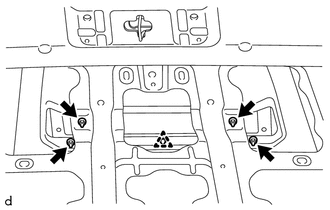
(b) Disengage the clip from back side of the hood panel to remove the hood bulge assembly together with the air intake guide.
2. REMOVE NO. 2 HOOD BULGE PROTECTOR (w/ Hood Bulge)
|
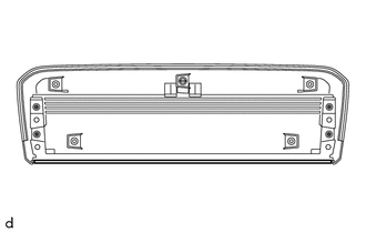
(a) Remove the No. 2 hood bulge protector. |
|
3. REMOVE HOOD AIR INTAKE GUIDE (w/ Hood Bulge)
|
(a) Remove the 4 screws. |
|
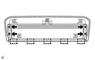
(b) Disengage the 5 guides to remove the hood air intake guide.
4. REMOVE NO. 1 HOOD BULGE PROTECTOR (w/ Hood Bulge)
|
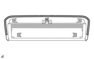
(a) Remove the No. 1 hood bulge protector. |
|
5. REMOVE HOOD TO RADIATOR SUPPORT SEAL
|
(a) Using a clip remover, remove the 7 clips and hood to radiator support seal. |
|
6. REMOVE WASHER NOZZLE SUB-ASSEMBLY
.gif)
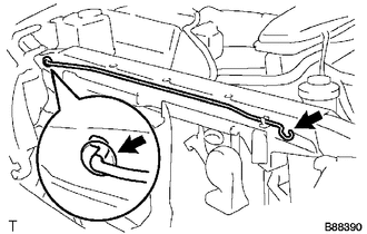
7. DISCONNECT WASHER HOSE ASSEMBLY
|
(a) Disengage the 4 clamps to disconnect the washer hose assembly. |
|
|
(b) Disengage the 4 claws to remove the 4 clamps. |
|
8. REMOVE RADIATOR GRILLE
9. REMOVE HOOD LOCK ASSEMBLY
10. REMOVE HOOD SUPPORT
|
(a) Remove the hood support. |
|
(b) Remove the grommet.
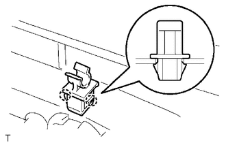
11. REMOVE HOOD STAY HOLDER
|
(a) Using a clip remover, disengage the 2 claws to remove the hood stay holder. |
|
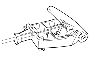
12. REMOVE HOOD LOCK CONTROL LEVER SUB-ASSEMBLY
|
(a) Disengage the claw and 3 guides to remove the hood lock control lever sub-assembly. |
|
|
(b) Disconnect the hood lock control cable assembly to remove the hood lock control lever sub-assembly. |
|
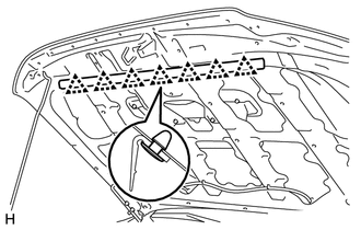
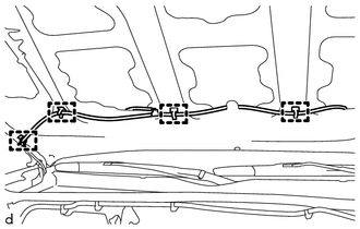
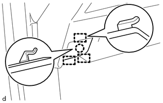
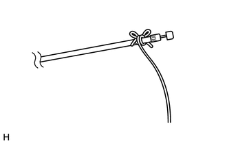
13. REMOVE HOOD LOCK CONTROL CABLE ASSEMBLY
|
(a) Tie a string to the end of the hood lock control cable assembly. HINT: Using a length of string long enough to pass through the motor compartment. |
|
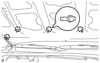
(b) Disengage the 5 clamps and hood cable grommet as shown in the illustration.
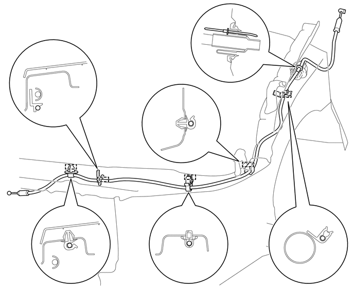
(c) Pull the hood lock control cable assembly from the engine compartment to remove it.
(d) Remove the string from the hood lock control cable assembly.
 Components
COMPONENTS
ILLUSTRATION
ILLUSTRATION
ILLUSTRATION
...
 Reassembly
REASSEMBLY
CAUTION / NOTICE / HINT
NOTICE:
When installing the hood bulge protector, heat the hood bulge surface
using the infrared light.
Do not heat the hood bulge excessively.
...
Other materials:
Illumination Circuit
DESCRIPTION
Power is supplied to the radio and display receiver assembly and steering pad
switch assembly illumination when the light control switch is in the TAIL or HEAD
position.
WIRING DIAGRAM
CAUTION / NOTICE / HINT
NOTICE:
The vehicle is equipped with a Supplemental Restrain ...
Inspection
INSPECTION
PROCEDURE
1. INSPECT OIL PUMP RELIEF VALVE
(a) Coat the oil pump relief valve with engine oil and check that it
falls smoothly into the valve hole by its own weight.
If the valve does not fall smoothly, replace the timing chain cover assembly.
...
Installation
INSTALLATION
PROCEDURE
1. INSTALL TRANSFER POSITION SWITCH
(a) Attach the 2 claws to install the transfer position switch.
2. INSTALL AIR CONDITIONING CONTROL ASSEMBLY (for Automatic Air Conditioning
System)
(See page )
3. INSTALL INTEGRATION PANEL SUB-ASSEMBLY (for Manual Cooler System)
...
