Toyota Tacoma (2015-2018) Service Manual: Removal
REMOVAL
PROCEDURE
1. REMOVE INTAKE MANIFOLD
(See page .gif) )
)
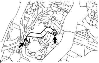
2. REMOVE WIRE HARNESS CLAMP BRACKET
|
(a) Remove the 2 bolts and wire harness clamp bracket. |
|
3. REMOVE FUEL TUBE SUB-ASSEMBLY
|
(a) Disconnect the fuel tube sub-assembly from the fuel pump assembly
(See page |
|
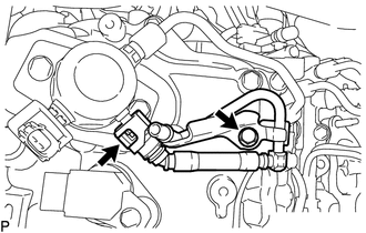
(b) Remove the bolt and fuel tube sub-assembly.
4. REMOVE NO. 1 FUEL PIPE SUB-ASSEMBLY
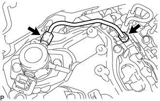
(a) Loosen the 2 union nuts of the No. 1 fuel pipe sub-assembly.
(b) Remove the No. 1 fuel pipe sub-assembly.
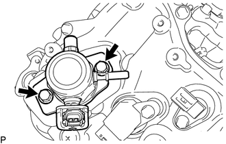
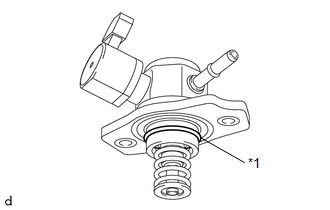
5. REMOVE FUEL PUMP ASSEMBLY
|
(a) Remove the 2 bolts and fuel pump assembly. |
|
|
(b) Remove the O-ring from the fuel pump assembly. |
|
(c) Remove the fuel pump lifter guide and fuel pump lifter assembly.
(d) Remove the fuel pump spacer gasket from the cylinder head cover sub-assembly.
 On-vehicle Inspection
ON-VEHICLE INSPECTION
PROCEDURE
1. CHECK FUEL PUMP ASSEMBLY OPERATION
(a) Check fuel pressure.
(1) Connect the Techstream to the DLC3.
(2) Start the engine.
(3) Turn the Techstream on.
(4) Ente ...
 Inspection
INSPECTION
PROCEDURE
1. INSPECT FUEL PUMP ASSEMBLY
(a) Measure the resistance according to the value(s) in the table below.
Standard Resistance:
Tester Connection
Condition ...
Other materials:
Multi-terrain Select Switch
Components
COMPONENTS
ILLUSTRATION
Removal
REMOVAL
PROCEDURE
1. REMOVE MULTI-TERRAIN SELECT SWITCH (DRIVE MONITOR SWITCH)
(a) Disengage the 2 claws to remove the multi-terrain select switch (drive
monitor switch).
Inspection ...
Definition Of Terms
DEFINITION OF TERMS
Term
Definition
Monitor Description
Description of what the ECM monitors and how it detects malfunctions
(monitoring purpose and details).
Related DTCs
A group of diagnostic trouble codes that are ...
Front Camera Module Incorrect Axial Gap (C1AA8,C1AA9)
DESCRIPTION
If the forward recognition camera detects that the forward recognition camera
axis has deviated, DTC C1AA8 is stored. Also, if Forward Recognition Camera Axis
Adjustment is not performed after installing the forward recognition camera, DTC
C1AA9 is stored.
DTC No.
...
