Toyota Tacoma (2015-2018) Service Manual: Disassembly
DISASSEMBLY
PROCEDURE
1. REMOVE REAR AXLE SHAFT SNAP RING
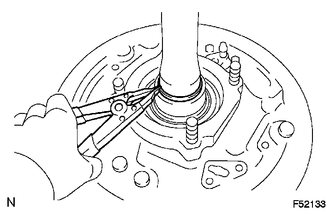
(a) Using a snap ring expander, remove the snap ring.
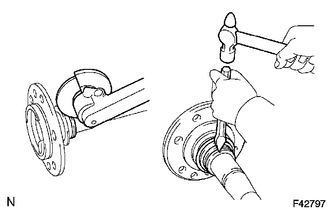
2. REMOVE REAR AXLE SHAFT
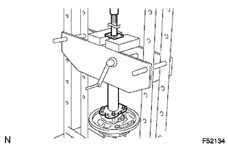
(a) Using SST and press, remove the rear axle shaft.
SST: 09521-25011
SST: 09521-25021
3. REMOVE REAR AXLE BEARING RETAINER INNER
(a) Remove the rear axle bearing retainer inner from the rear axle bearing.
4. REMOVE REAR AXLE SHAFT WASHER
(a) Remove the rear axle shaft washer from the rear axle bearing.
5. REMOVE REAR AXLE HUB AND BEARING ASSEMBLY
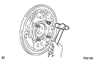
(a) Attach the 4 nuts to the rear axle housing bolts.
(b) Using a hammer, remove the 4 rear axle housing bolts and rear axle bearing.
NOTICE:
Do not reuse the nuts previously removed from the vehicle.
6. REMOVE REAR AXLE HUB BOLT
|
(a) Using SST, remove the 6 hub bolts. SST: 09650-17011 |
|
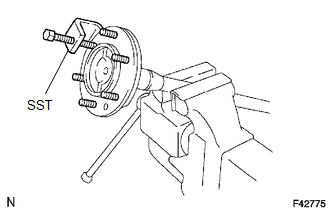
(b) Remove the deflector and deflector gasket from the rear axle shaft.
7. REMOVE REAR AXLE BEARING OIL SEAL
(a) Grind the rear axle bearing inner race surface using a grinder, and then chisel them out with a chisel.
(b) Remove the rear axle shaft oil seal from the rear axle shaft.
 Components
COMPONENTS
ILLUSTRATION
ILLUSTRATION
...
 Inspection
INSPECTION
PROCEDURE
1. INSPECT REAR AXLE SHAFT
(a) Using a dial indicator, measure the runout of the shaft and flange.
Maximum runout:
Shaft runout: 1.5 mm (0.0591 in.)
Flange runout: 0.05 m ...
Other materials:
Adjustment
ADJUSTMENT
CAUTION / NOTICE / HINT
HINT:
Use the same procedures for both the LH and RH sides.
The procedure described below is for the LH side.
Centering bolts are used to mount the door hinge to the vehicle body
and door. The door cannot be adjusted with the centering bolts ...
Transfer Shift Motor Limit Switch Circuit (P17AC)
DESCRIPTION
When the transfer switches modes, the TL1, TL2 and TL3 terminals of the limit
switch are in one of the ON/OFF combinations listed in the table below.
Terminal
When 2WD
Switching between 2WD and H4
When H4
Switching between H4 and ...
Stop Light Switch OFF Stuck Malfunction (C1426)
DESCRIPTION
The skid control ECU (brake actuator assembly) inputs the stop light signal and
brake operation condition. When the brake pedal is depressed and the stop light
switch signal is not input, C1426 is output.
DTC No.
Detection Item
DTC Detection Conditi ...
