Toyota Tacoma (2015-2018) Service Manual: Components
COMPONENTS
ILLUSTRATION
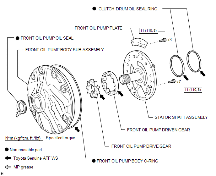
 Oil Pump
...
 Disassembly
DISASSEMBLY
PROCEDURE
1. REMOVE FRONT OIL PUMP BODY O-RING
(a) Remove the front oil pump body O-ring from the oil pump assembly.
2. SECURE OIL ...
Other materials:
Installation
INSTALLATION
PROCEDURE
1. INSTALL FRONT DIFFERENTIAL CARRIER ASSEMBLY
(a) Connect the actuator hose and connector.
(b) Install the No. 1 mounting support with the 3 bolts.
Torque:
186 N·m {1899 kgf·cm, 138 ft·lbf}
(c) Install the No. 2 mounting support with the 2 bolts.
Torque:
160 N ...
Removal
REMOVAL
CAUTION / NOTICE / HINT
NOTICE:
Replace the blind spot monitor sensor if it has been dropped or subjected to
a severe impact.
PROCEDURE
1. REMOVE REAR BUMPER ASSEMBLY (w/ Towing Package)
(See page )
2. REMOVE REAR BUMPER ASSEMBLY (w/o Towing Package)
(See page )
3. REMOVE CONN ...
Data List / Active Test
DATA LIST / ACTIVE TEST
1. DATA LIST
HINT:
Using the Techstream to read the Data List allows the values or states of switches,
sensors, actuators and other items to be read without removing any parts. This non-intrusive
inspection can be very useful because intermittent conditions or signals ...
