Toyota Tacoma (2015-2018) Service Manual: Cruise Control Switch Circuit
DESCRIPTION
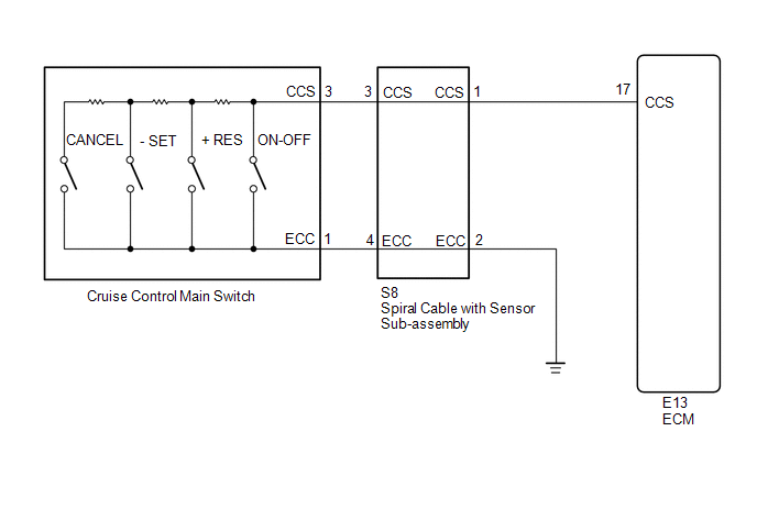
This circuit sends signals to the ECM depending on the cruise control main switch condition.
The battery supplies the positive (+) battery voltage to the cruise control main switch. Then terminal CCS of the ECM receives the voltage as the signal according to the switch condition.
WIRING DIAGRAM
PROCEDURE
|
1. |
INSPECT CRUISE CONTROL MAIN SWITCH |
(a) Remove the cruise control main switch (See page
.gif) ).
).
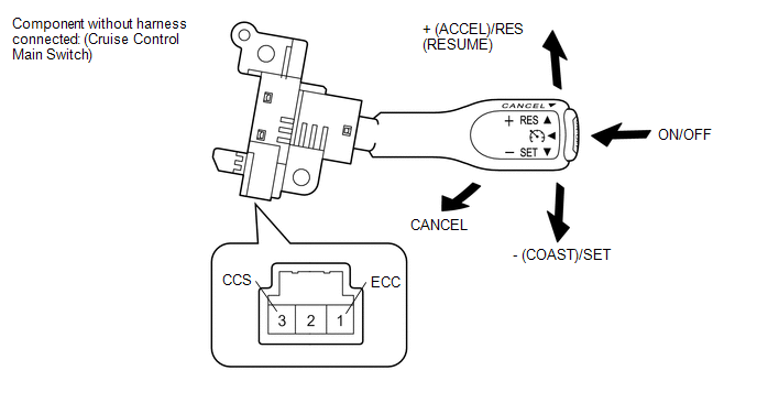
(b) Measure the resistance according to the value(s) in the table below.
Standard Resistance:
|
Tester Connection |
Switch Condition |
Specified Condition |
|---|---|---|
|
1 - 3 |
+ (ACCEL)/RES (RESUME) |
235 to 245 Ω |
|
1 - 3 |
- (COAST)/SET |
617 to 643 Ω |
|
1 - 3 |
CANCEL |
1,509 to 1,571 Ω |
|
1 - 3 |
Main Switch OFF |
10 kΩ or higher |
|
1 - 3 |
Main Switch ON |
Below 1 Ω |
(c) Reinstall the cruise control main switch.
| NG | .gif) |
REPLACE CRUISE CONTROL MAIN SWITCH |
|
.gif)
|
2. |
CHECK HARNESS AND CONNECTOR (CRUISE CONTROL MAIN SWITCH - SPIRAL CABLE WITH SENSOR SUB-ASSEMBLY) |
|
(a) Disconnect the spiral cable with sensor sub-assembly side and main switch side connector. |
|
(b) Measure the resistance according to the value(s) in the table below.
Standard Resistance:
|
Tester Connection |
Condition |
Specified Condition |
|---|---|---|
|
1 (main switch side) - 3 (spiral cable with sensor sub-assembly side) |
Always |
Below 1 Ω |
|
3 (main switch side) - 4 (spiral cable with sensor sub-assembly side) |
Always |
Below 1 Ω |
|
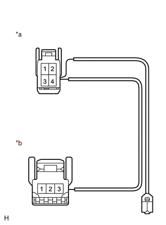
*a |
Front view of wire harness connector (to Spiral Cable with Sensor Sub-assembly) |
|
*b |
Front view of wire harness connector (to Cruise Control Main Switch) |
(c) Reconnect the spiral cable with sensor sub-assembly side and main switch side connector.
| NG | |
REPAIR OR REPLACE HARNESS OR CONNECTOR |
|
|
3. |
INSPECT SPIRAL CABLE WITH SENSOR SUB-ASSEMBLY |
NOTICE:
The spiral cable with sensor sub-assembly is an important part of the SRS airbag system. Incorrect removal or installation of the spiral cable with sensor sub-assembly may prevent the airbag from deploying. Be sure to read the page shown in the brackets.
HINT:
- Removal (See page ).
- Installation (See page ).
(a) Remove the spiral cable with sensor sub-assembly.
(b) Measure the resistance according to the value(s) in the table below.
Standard Resistance:
|
Tester Connection |
Condition |
Specified Condition |
|---|---|---|
|
3 (CCS) main switch side - S8-1 (CCS) |
The spiral cable with sensor sub-assembly position is center |
Below 1 Ω |
|
The spiral cable with sensor sub-assembly position is 2.5 rotations to the left |
||
|
The spiral cable with sensor sub-assembly position is 2.5 rotations to the right |
||
|
4 (ECC) main switch side - S8-2 (ECC) |
The spiral cable with sensor sub-assembly position is center |
Below 1 Ω |
|
The spiral cable with sensor sub-assembly position is 2.5 rotations to the left |
||
|
The spiral cable with sensor sub-assembly position is 2.5 rotations to the right |
|
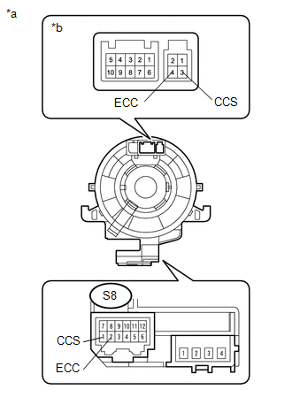
*a |
Component without harness connected (Spiral Cable with Sensor Sub-assembly) |
|
*b |
Cruise Control Main Switch Side |
(c) Reinstall the spiral cable with sensor sub-assembly.
| NG | |
REPLACE SPIRAL CABLE WITH SENSOR SUB-ASSEMBLY |
|
|
4. |
CHECK HARNESS AND CONNECTOR (SPIRAL CABLE WITH SENSOR SUB-ASSEMBLY - ECM AND BODY GROUND) |
(a) Disconnect the E13 ECM connector.
(b) Disconnect the S8 spiral cable with sensor sub-assembly connector.
(c) Measure the resistance according to the value(s) in the table below.
Standard Resistance:
|
Tester Connection |
Condition |
Specified Condition |
|---|---|---|
|
S8-2 (ECC) - Body Ground |
Always |
Below 1 Ω |
Standard Resistance:
|
Tester Connection |
Condition |
Specified Condition |
|---|---|---|
|
E13-17 (CCS) - S8-1 (CCS) |
Always |
Below 1 Ω |
|
E13-17 (CCS) - Body ground |
Always |
10 kΩ or higher |
(d) Reconnect the ECM connector.
(e) Reconnect the spiral cable with sensor sub-assembly connector.
| OK | |
PROCEED TO NEXT SUSPECTED AREA SHOWN IN PROBLEM SYMPTOMS TABLE |
| NG | |
REPAIR OR REPLACE HARNESS OR CONNECTOR |
 Cruise Control Input Processor (P160700)
DESCRIPTION
When the ECM determines that there is a malfunction, the ECM illuminates the
MIL and stores a DTC.
HINT:
When these DTCs are stored, the ECM cuts the current supplied to the throttle ...
 Cruise Main Indicator Light Circuit
DESCRIPTION
When the ECM detects a cruise control switch on signal from the cruise
control switch, the ECM sends the signal to the combination meter assembly
through CAN communication. ...
Other materials:
Main Switch Power Source Circuit
DESCRIPTION
This circuit supplies power to the wireless charger main switch (mobile wireless
charger switch) and illuminates the switch indicator light when the wireless charger
main switch (mobile wireless charger switch) is turned on.
WIRING DIAGRAM
CAUTION / NOTICE / HINT
NOTICE:
Inspe ...
Dtc Check / Clear
DTC CHECK / CLEAR
1. CHECK DTC
(a) Check the DTCs.
(1) Turn the ignition switch off.
(2) Connect the Techstream to the DLC3.
(3) Turn the ignition switch to ON.
(4) Turn the Techstream on.
(5) Read the DTCs following the prompts on the Techstream screen. Enter the following
menus: Powertrai ...
Reassembly
REASSEMBLY
PROCEDURE
1. INSTALL RADIATOR GRILLE MOULDING
(a) Engage the 8 claws to install the radiator grille moulding.
(b) Install the 8 screws.
2. INSTALL NO. 1 RADIATOR GRILLE GARNISH
(a) for Type A and Type B:
(1) Engag ...
