Toyota Tacoma (2015-2018) Service Manual: Crankshaft Position Sensor
Components
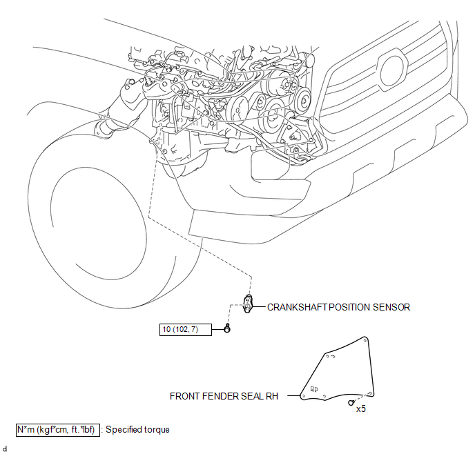
COMPONENTS
ILLUSTRATION
Installation
INSTALLATION
PROCEDURE
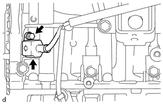
1. INSTALL CRANKSHAFT POSITION SENSOR
(a) Apply a light coat of engine oil to the O-ring of the crankshaft position sensor.
NOTICE:
- When reusing the crankshaft position sensor, inspect the O-ring.
- If the O-ring has scratches or cuts, replace the crankshaft position sensor.
(b) Install the crankshaft position sensor to the cylinder block sub-assembly with the bolt.
Torque:
10 N·m {102 kgf·cm, 7 ft·lbf}
(c) Connect the connector to the crankshaft position sensor.
2. INSTALL FRONT FENDER SEAL RH
HINT:
Use the same procedure as for the LH side (See page
.gif) ).
).
Removal
REMOVAL
PROCEDURE
1. REMOVE FRONT FENDER SEAL RH
HINT:
Use the same procedure as for the LH side (See page
.gif) ).
).
2. REMOVE CRANKSHAFT POSITION SENSOR
|
(a) Disconnect the connector from the crankshaft position sensor. |
|
(b) Remove the bolt and crankshaft position sensor from the cylinder block sub-assembly.
 Installation
INSTALLATION
PROCEDURE
1. SET NO. 1 CYLINDER TO TDC/COMPRESSION
2. INSTALL CAMSHAFT TIMING GEAR BOLT
NOTICE:
There are different types of camshaft timing gearbolts. Make sure to check the
id ...
 Ecm
Ecm
Components
COMPONENTS
ILLUSTRATION
ILLUSTRATION
Installation
INSTALLATION
PROCEDURE
1. INSTALL NO. 2 ECM BRACKET
(a) Install the No. 2 ECM bracket to the ECM with the 2 screws.
Torque ...
Other materials:
Installation
INSTALLATION
PROCEDURE
1. INSTALL PARK/NEUTRAL POSITION SWITCH
HINT:
Make sure that the manual valve lever shaft has not been rotated prior to installing
the park/neutral position switch as the detent spring may become detached from the
manual valve lever shaft.
(a) Clean the bolt and bolt ...
Stereo Component Amplifier Malfunction (B15A3)
DESCRIPTION
This DTC is stored when a malfunction occurs in the stereo component amplifier
assembly.
DTC No.
DTC Detection Condition
Trouble Area
B15A3
When one of the conditions below is met:
Internal power supply malfun ...
Installation
INSTALLATION
CAUTION / NOTICE / HINT
CAUTION:
Be sure to perform this procedure with several people as the transfer assembly
is very heavy.
PROCEDURE
1. INSTALL TRANSFER CASE LOWER PROTECTOR
(a) Install the transfer case lower protector with the 4 bolts.
Torque:
18 N·m {184 kgf·cm, 13 f ...
