Toyota Tacoma (2015-2018) Service Manual: Ecm
Components
COMPONENTS
ILLUSTRATION
ILLUSTRATION
Installation
INSTALLATION
PROCEDURE
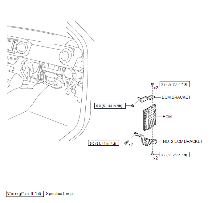
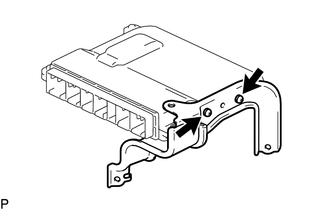
1. INSTALL NO. 2 ECM BRACKET
(a) Install the No. 2 ECM bracket to the ECM with the 2 screws.
Torque:
3.2 N·m {33 kgf·cm, 28 in·lbf}
2. INSTALL ECM BRACKET
(a) Install the ECM bracket to the ECM with the 2 screws.
Torque:
3.2 N·m {33 kgf·cm, 28 in·lbf}
3. INSTALL ECM
(a) Install the ECM to the instrument panel reinforcement assembly with the 2 bolts and nut.
Torque:
5.0 N·m {51 kgf·cm, 44 in·lbf}
(b) Connect the 6 connectors.
(c) Engage the clamp to install the wire harness.
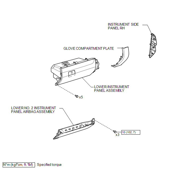
4. INSTALL LOWER INSTRUMENT PANEL ASSEMBLY
.gif)
5. INSTALL LOWER NO. 2 INSTRUMENT PANEL AIRBAG ASSEMBLY
6. INSTALL GLOVE COMPARTMENT PLATE
7. INSTALL INSTRUMENT SIDE PANEL RH
8. CONNECT CABLE TO NEGATIVE BATTERY TERMINAL
Torque:
5.4 N·m {55 kgf·cm, 48 in·lbf}
NOTICE:
When disconnecting the cable, some systems need to be initialized after the cable is reconnected.
Click here
9. PERFORM SRS WARNING LIGHT
(See page )
10. PERFORM INITIALIZATION
Click here
Removal
REMOVAL
PROCEDURE
1. PRECAUTION
CAUTION:
Be sure to read Precaution thoroughly before servicing (See page
.gif) ).
).
NOTICE:
After turning the ignition switch off, waiting time may be required before disconnecting
the cable from the negative (-) battery terminal. Therefore, make sure to read the
disconnecting the cable from the negative (-) battery terminal notices before proceeding
with work (See page ).
2. DISCONNECT CABLE FROM NEGATIVE BATTERY TERMINAL
NOTICE:
When disconnecting the cable, some systems need to be initialized after the cable is reconnected.
Click here
3. REMOVE INSTRUMENT SIDE PANEL RH
4. REMOVE GLOVE COMPARTMENT PLATE
5. REMOVE LOWER NO. 2 INSTRUMENT PANEL AIRBAG ASSEMBLY
6. REMOVE LOWER INSTRUMENT PANEL ASSEMBLY
7. REMOVE ECM
|
(a) Disengage the clamp to separate the wire harness. |
|
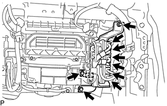
(b) Disconnect the 6 connectors.
(c) Remove the 2 bolts, nut and ECM from the instrument panel reinforcement assembly.
8. REMOVE ECM BRACKET
|
(a) Remove the 2 screws and ECM bracket from the ECM. |
|
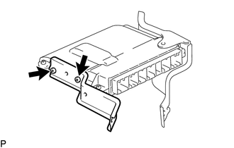
9. REMOVE NO. 2 ECM BRACKET
|
(a) Remove the 2 screws and No. 2 ECM bracket from the ECM. |
|
 Crankshaft Position Sensor
Components
COMPONENTS
ILLUSTRATION
Installation
INSTALLATION
PROCEDURE
1. INSTALL CRANKSHAFT POSITION SENSOR
(a) Apply a light coat of engine oil to the O-ring of the crankshaft position ...
 Engine Coolant Temperature Sensor
Components
COMPONENTS
ILLUSTRATION
Inspection
INSPECTION
PROCEDURE
1. INSPECT ENGINE COOLANT TEMPERATURE SENSOR
(a) Partially immerse the engine coolant temperature sensor in water and wa ...
Other materials:
Disassembly
DISASSEMBLY
PROCEDURE
1. FIX VANE PUMP ASSEMBLY
(a) Using SST, fix the vane pump assembly in a vise.
SST: 09630-00014
09631-00132
NOTICE:
When using a vise, do not overtighten it.
2. REMOVE POWER STEERING SUCTION PORT UNION
...
USB Audio System Recognition/Play Error
DESCRIPTION
When a USB device or "iPod" is connected to the USB jack of the No. 1 stereo
jack adapter assembly, it must have playable files. The device must also communicate
with and be recognized by the radio and display receiver assembly. This diagnosis
procedure is for when a dev ...
How To Proceed With Troubleshooting
CAUTION / NOTICE / HINT
HINT:
Use the following procedure to troubleshoot the air conditioning system.
*: Use the Techstream.
PROCEDURE
1.
VEHICLE BROUGHT TO WORKSHOP
NEXT
...
