Toyota Tacoma (2015-2018) Service Manual: Components
COMPONENTS
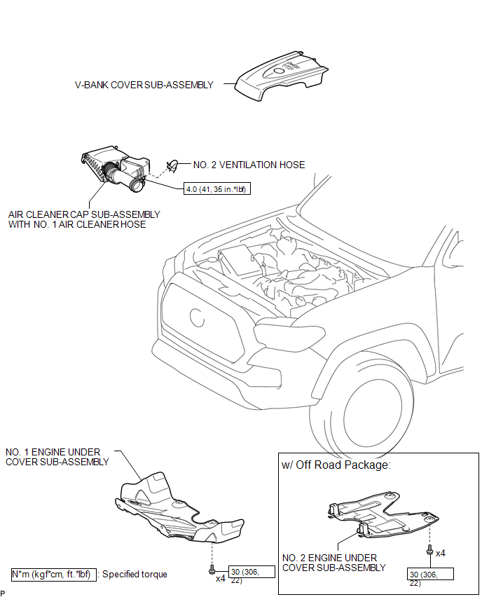
ILLUSTRATION
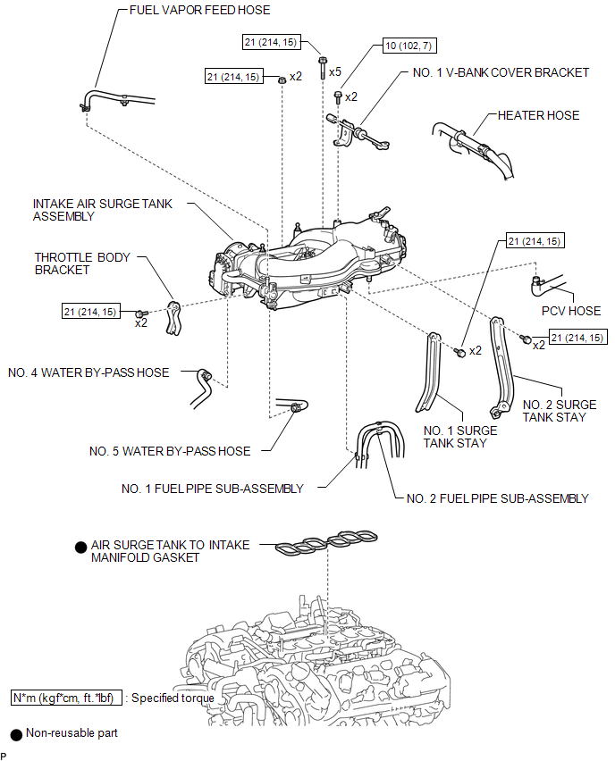
ILLUSTRATION
ILLUSTRATION
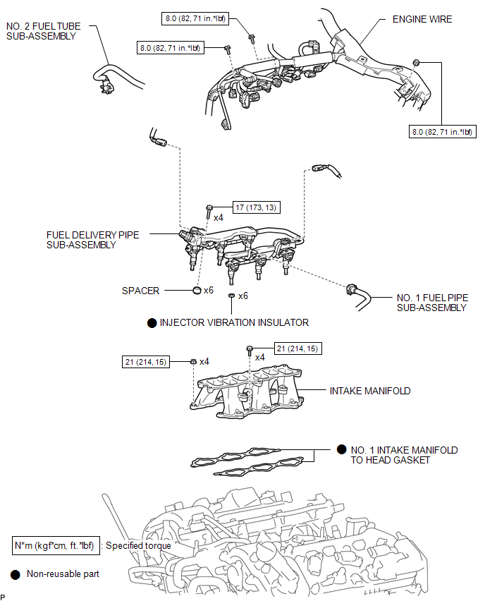
 Intake Manifold
...
 Installation
INSTALLATION
PROCEDURE
1. INSTALL INTAKE MANIFOLD
(a) Set 2 new No. 1 intake manifold to head gaskets on cylinder head
sub-assembly and cylinder head LH as shown in the illustration. ...
Other materials:
Problem Symptoms Table
PROBLEM SYMPTOMS TABLE
HINT:
Use the table below to help determine the cause of problem symptoms.
If multiple suspected areas are listed, the potential causes of the symptoms
are listed in order of probability in the "Suspected Area" column of the
table. Check each sy ...
Inspection
INSPECTION
PROCEDURE
1. REMOVE SPIRAL CABLE SUB-ASSEMBLY WITH SENSOR
(a) If there are any defects as mentioned below, replace the spiral cable sub-assembly
with a new one:
Scratches, cracks, dents or chips on the connector or the spiral cable sub-assembly.
(b) Inspect the spiral ca ...
Transmitter Battery(w/ Smart Key System)
Replacement
REPLACEMENT
CAUTION / NOTICE / HINT
NOTICE:
Take extra care when handling these precision electronic components.
PROCEDURE
1. REMOVE TRANSMITTER BATTERY
(a) Push the release hook knob and extract the mechanical key as shown
in the illustration.
Text in Illustra ...
