Toyota Tacoma (2015-2018) Service Manual: Removal
REMOVAL
CAUTION / NOTICE / HINT
NOTICE:
Release the vacuum from booster by depressing the brake pedal several times.
Then remove the brake master cylinder from brake booster.
PROCEDURE
1. PRECAUTION
NOTICE:
After turning the ignition switch off, waiting time may be required before disconnecting the cable from the negative (-) battery terminal. Therefore, make sure to read the disconnecting the cable from the negative (-) battery terminal notices before proceeding with work.
Click here .gif)
2. DISCONNECT CABLE FROM NEGATIVE BATTERY TERMINAL
NOTICE:
When disconnecting the cable, some systems need to be initialized after the cable is reconnected.
Click here
3. REMOVE LOWER NO. 1 INSTRUMENT PANEL AIRBAG ASSEMBLY
Click here
4. REMOVE BRAKE MASTER CYLINDER SUB-ASSEMBLY
Click here
5. SEPARATE MASTER CYLINDER PUSH ROD CLEVIS
Click here
6. REMOVE BRAKE BOOSTER ASSEMBLY
|
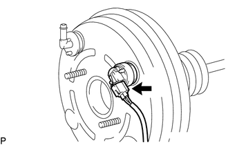
(a) Disconnect the vacuum warning switch assembly connector. (for 2GR-FKS) |
|
|
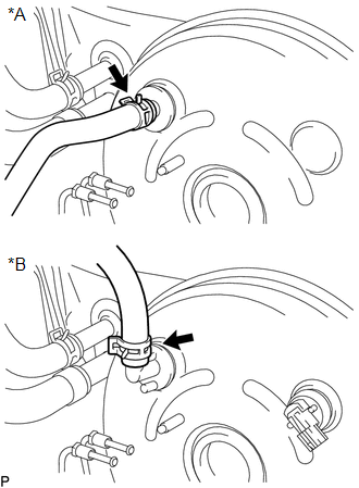
(b) Disconnect the vacuum hose from the brake booster assembly. Text in Illustration
|
|
|
(c) Remove the 4 nuts, and pull out the brake booster assembly. |
|
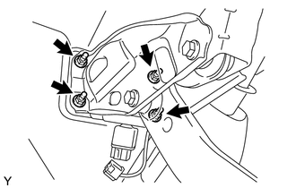
(d) Remove the gasket from the brake booster assembly.
(e) Loosen the lock nut and then remove the push rod clevis.
7. REMOVE BRAKE VACUUM CHECK VALVE ASSEMBLY
|
(a) Remove the vacuum check valve from the brake booster assembly. Text in Illustration
|
|
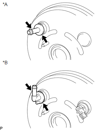
(b) Remove the grommet from the brake booster assembly.
8. REMOVE VACUUM WARNING SWITCH ASSEMBLY (for 2GR-FKS)
Click here
 On-vehicle Inspection
ON-VEHICLE INSPECTION
PROCEDURE
1. CHECK BRAKE BOOSTER ASSEMBLY
(a) Airtightness check.
Text in Illustration
*a
Correct
...
 Inspection
INSPECTION
PROCEDURE
1. INSPECT BRAKE VACUUM CHECK VALVE ASSEMBLY
(a) Check that there is ventilation from the booster to the engine, and
no ventilation from the engine to the booste ...
Other materials:
Dtc Check / Clear
DTC CHECK / CLEAR
CHECK DTC
(a) Connect the Techstream to the DLC3.
(b) Turn the ignition switch to ON.
(c) Turn the Techstream on.
(d) Enter the following menus: Body Electrical / Pre-Collision 2 / Trouble Codes.
(e) Check for DTCs.
Click here
CLEAR DTC
(a) Connect the Techstream to the ...
Inspection
INSPECTION
PROCEDURE
1. INSPECT TRANSMISSION WIRE
(a) Measure the resistance according to the value(s) in the table below.
Text in Illustration
*a
Component without harness connected
(Transmission Wire)
Standard Resistance: ...
Vacuum Pump
Components
COMPONENTS
ILLUSTRATION
Installation
INSTALLATION
PROCEDURE
1. INSTALL VACUUM PUMP ASSEMBLY
(a) Apply engine oil to the 2 O-rings on the vacuum pump assembly.
(b) Apply engine oil to the inner surface of the installation hole.
(c) Install the vacuum pump assembly so that th ...
