Toyota Tacoma (2015-2018) Service Manual: Components
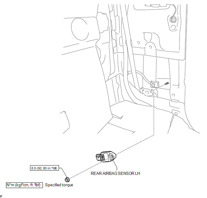
COMPONENTS
ILLUSTRATION

 On-vehicle Inspection
ON-VEHICLE INSPECTION
PROCEDURE
1. INSPECT REAR AIRBAG SENSOR (for Vehicle not Involved in Collision)
(a) Perform a diagnostic system check (See page
).
2. INSPECT REAR AIRBAG SENSOR (for Vehicl ...
Other materials:
Dtc Check / Clear
DTC CHECK / CLEAR
1. CHECK DTC
(a) Check the DTCs.
(1) Turn the ignition switch off.
(2) Connect the Techstream to the DLC3.
(3) Turn the ignition switch to ON.
(4) Turn the Techstream on.
(5) Read the DTCs following the prompts on the Techstream screen. Enter the following
menus: Powertrai ...
Steering Angle Sensor Power Source Voltage Malfunction (C1432)
DESCRIPTION
Steering angle sensor (spiral cable with sensor sub-assembly) signals are sent
to the skid control ECU (master cylinder solenoid) via the CAN communication system.
When there is a malfunction in the CAN communication system, it is detected by the
steering angle sensor zero point m ...
Steering Pad Switch
Components
COMPONENTS
ILLUSTRATION
Removal
REMOVAL
PROCEDURE
1. REMOVE STEERING PAD
(See page
)
2. REMOVE STEERING PAD SWITCH ASSEMBLY
(a) Disconnect the 2 connectors.
(b) Disengage the 2 clamps.
(c) Remove the 4 screws.
...
