Toyota Tacoma (2015-2018) Service Manual: Disassembly
DISASSEMBLY
PROCEDURE
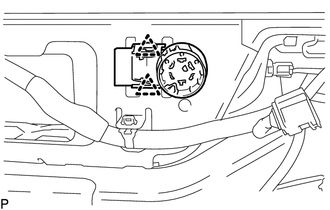
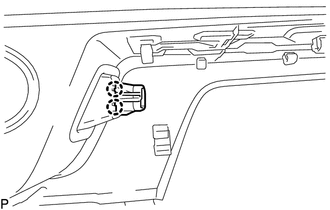
1. REMOVE CONNECTOR COVER
|
(a) Disengage the 2 clips to remove the connector cover. |
|
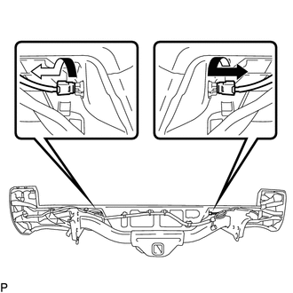
2. REMOVE REAR BUMPER PAD SUB-ASSEMBLY
|
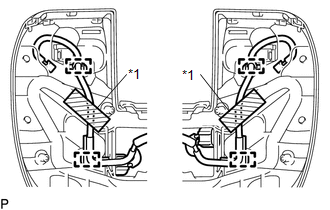
(a) Separate the 2 license plate light assemblies as shown in the illustration. |
|
|
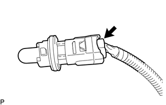
(b) Disconnect the connector to remove the license plate light socket. HINT: Use the same procedure for the RH side and LH side. |
|
(c) w/ Clearance Sonar System:
(1) Remove the 3 clips.
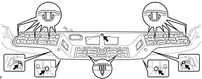
(2) Disengage the 14 claws to separate the rear bumper pad sub-assembly.
(3) Disconnect the 2 connectors to remove the rear bumper pad sub-assembly.
(d) w/o Clearance Sonar System:
(1) Remove the 3 clips.
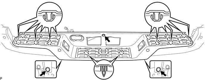
(2) Disengage the 14 claws to remove the rear bumper pad sub-assembly.
|
(e) Disengage the 2 claws to remove the license plate light lens. HINT: Use the same procedure for the RH side and LH side. |
|
3. REMOVE NO. 1 ULTRASONIC SENSOR (w/ Clearance Sonar System)
.gif)
4. REMOVE REAR BUMPER PLATE
(a) Disengage the wire harness clamps.
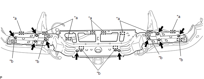 Text in Illustration
|
*a |
Wire Harness Clamp |
*b |
Guide |
(b) Remove the 10 bolts.
(c) Disengage the 6 guides to remove the rear bumper plate.
5. REMOVE REAR BUMPER EXTENSION LH
|
(a) Remove the 5 clips. Text in Illustration
|
|
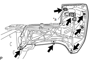
(b) Remove the clamp.
(c) w/ Clearance Sonar System:
(1) Disconnect the connector.
(d) Remove the rear bumper extension LH.
6. REMOVE REAR BUMPER EXTENSION RH
HINT:
Use the same procedure as for the LH side.
7. REMOVE NO. 1 ULTRASONIC SENSOR (w/ Clearance Sonar System)
8. REMOVE BLIND SPOT MONITOR SENSOR LH (w/ Blind Spot Monitor)
|
(a) Disconnect the connector. |
|
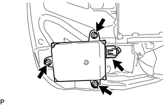
(b) Remove the 3 nuts and blind spot monitor sensor LH.
9. REMOVE BLIND SPOT MONITOR SENSOR RH (w/ Blind Spot Monitor)
HINT:
Use the same procedure as for the LH side.
10. REMOVE NO. 6 FLOOR WIRE
|
(a) Remove the 2 adhesive tapes. Text in Illustration
|
|
(b) Disengage the wire harness clamps to remove the No. 6 floor wire.
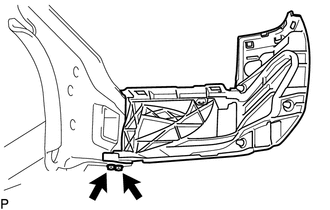
11. REMOVE REAR BUMPER SIDE STAY LH
|
(a) Remove the 2 bolts and rear bumper side stay LH. |
|
12. REMOVE REAR BUMPER SIDE STAY RH
HINT:
Use the same procedure as for the LH side.
 Removal
REMOVAL
CAUTION / NOTICE / HINT
HINT:
If the bumper is damaged, there is a possibility that the installation area of
the blind spot monitor sensor may be deformed and the blind spot monitor syste ...
 Reassembly
REASSEMBLY
PROCEDURE
1. INSTALL REAR BUMPER SIDE STAY LH
(a) Install the rear bumper side stay LH with the 2 bolts.
Torque:
30 N·m {306 kgf·cm, 22 ft·lbf}
...
Other materials:
Horn Relay
On-vehicle Inspection
ON-VEHICLE INSPECTION
PROCEDURE
1. INSPECT HORN RELAY ASSEMBLY
(a) Check the resistance.
(1) Measure the resistance according to the value(s) in the table below.
Standard Resistance:
Tester Connection
Connection
...
Inspection
INSPECTION
PROCEDURE
1. INSPECT MAGNET STARTER SWITCH ASSEMBLY
(a) Inspect the pull-in coil.
(1) Measure the resistance according to the value(s) in the table below.
Text in Illustration
*a
Terminal 50
*b
...
Blind Spot Monitor Master Module (C1AB6)
DESCRIPTION
This DTC is stored when the blind spot monitor sensor LH detects an internal
malfunction.
DTC Code
DTC Detection Condition
Trouble Area
C1AB6
The blind spot monitor sensor LH (master) detects an internal malfunction.
...
