Toyota Tacoma (2015-2018) Service Manual: Components
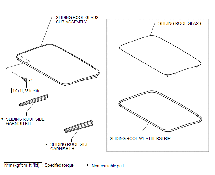
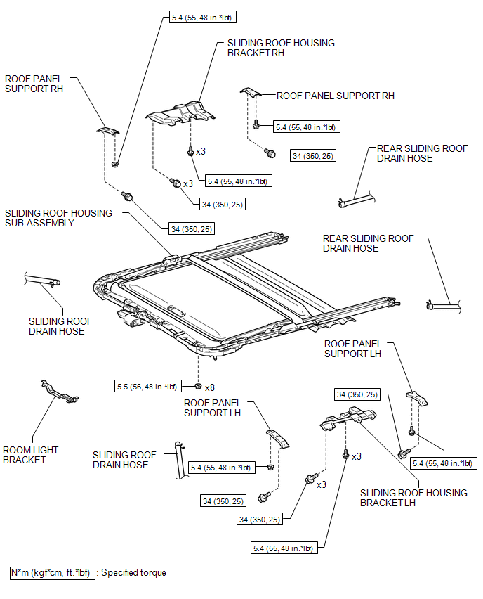
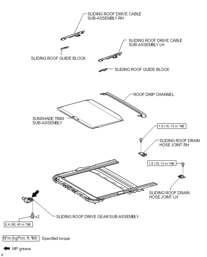
COMPONENTS
ILLUSTRATION
ILLUSTRATION
ILLUSTRATION

 Disassembly
DISASSEMBLY
PROCEDURE
1. REMOVE ROOM LIGHT BRACKET
(a) Disengage the guide to remove the room light bracket.
2. REMOVE SLIDING ROOF DRIVE GEAR ...
Other materials:
A/C ECU Vehicle Information Reading/Writing Processor Malfunction (B15F5)
DESCRIPTION
This DTC is stored when items controlled by the air conditioning amplifier assembly
cannot be customized via the audio and visual system vehicle customization screen.
HINT:
The air conditioning amplifier assembly controls the air conditioning system
related items that are customiz ...
Engine compartment
2.7 L 4-cylinder (2TR-FE) engine
1. Washer fluid tank
2.Radiator cap
3.Engine coolant reservoir
4. Engine oil filler cap
5. Power steering fluid reservoir
6. Engine oil level dipstick
7. Brake fluid reservoir
8. Fuse box
9. Battery
10. Condenser
11. Radiator
4.0 L V6 (1GR-FE) engine
...
Listening to a USB memory device
Connecting a USB memory device enables you to enjoy music from the vehicle
speakers.
Select “USB” on the “Select Audio Source” screen.
Connecting a USB memory device
Audio control screen
1. “Select Audio Source” screen appears
2. Displaying the folder list
3. Random playback
4 ...
