Toyota Tacoma (2015-2018) Service Manual: Disassembly
DISASSEMBLY
PROCEDURE
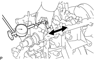
1. INSPECT CONNECTING ROD THRUST CLEARANCE
|
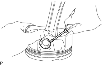
(a) Using a dial indicator, measure the thrust clearance while moving the connecting rod back and forth. Standard thrust clearance: 0.15 to 0.40 mm (0.00591 to 0.0157 in.) Maximum thrust clearance: 0.50 mm (0.0197 in.) If the thrust clearance is more than the maximum, replace the connecting rod assemblies as necessary. If necessary, replace the crankshaft. |
|
2. INSPECT CONNECTING ROD OIL CLEARANCE
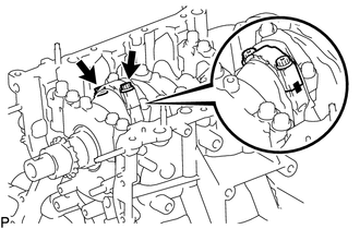
(a) Check that the matchmarks on the connecting rod sub-assembly and connecting rod cap are aligned.
HINT:
The matchmarks on the connecting rod sub-assembly and connecting rod cap are guides for correct reassembly.
|
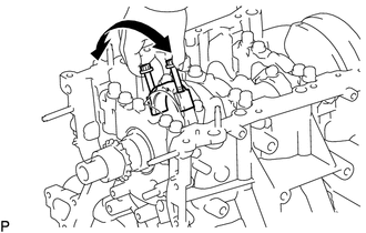
(b) Remove the 2 connecting rod cap bolts. |
|
|
(c) Using the 2 removed connecting rod cap bolts, remove the connecting rod cap and lower bearing by wiggling the connecting rod cap right and left. HINT: Keep the lower bearing inserted to the connecting rod cap. |
|
(d) Clean the crank pin and bearing.
(e) Check the crank pin and bearing for pitting and scratches.
|
(f) Lay a strip of Plastigage on the crank pin. Text in Illustration
|
|
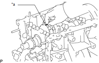
(g) Check that the front mark of the connecting rod cap is facing forward.
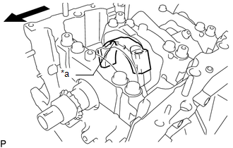 Text in Illustration
|
*a |
Front Mark |
.png) |
Engine Front |
(h) Install the connecting rod cap (See page .gif) ).
).
NOTICE:
Do not turn the crankshaft.
(i) Remove the 2 bolts and connecting rod cap.
(j) Measure the Plastigage at its widest point.
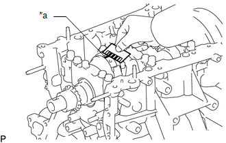 Text in Illustration
|
*a |
Plastigage |
Standard oil clearance:
0.032 to 0.052 mm (0.00126 to 0.00205 in.)
Maximum oil clearance:
0.070 mm (0.00276 in.)
If the oil clearance is more than the maximum, replace the connecting rod bearings. If necessary, inspect the crankshaft.
HINT:
If replacing a bearing, replace it with one that has the same number as its respective connecting rod cap. Each bearing standard thickness is indicated by a number (1, 2, 3 or 4) marked on its surface.
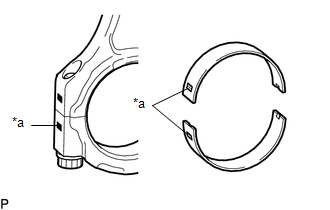 Text in Illustration
|
*a |
Number Mark |
Standard Connecting Rod Diameter:
|
Mark |
Specified Condition |
|---|---|
|
1 |
56.000 to 56.006 mm (2.20472 to 2.20496 in.) |
|
2 |
56.007 to 56.012 mm (2.20500 to 2.20519 in.) |
|
3 |
56.013 to 56.018 mm (2.20523 to 2.20543 in.) |
|
4 |
56.019 to 56.024 mm (2.20547 to 2.20566 in.) |
Standard Connecting Rod Bearing Center Wall Thickness:
|
Mark |
Specified Condition |
|---|---|
|
1 |
1.481 to 1.484 mm (0.05831 to 0.05843 in.) |
|
2 |
1.485 to 1.487 mm (0.05846 to 0.05854 in.) |
|
3 |
1.488 to 1.490 mm (0.05858 to 0.05866 in.) |
|
4 |
1.491 to 1.493 mm (0.05870 to 0.05878 in.) |
Standard crankshaft pin diameter:
52.992 to 53.000 mm (2.0863 to 2.0866 in.)
NOTICE:
Completely remove the Plastigage after the measurement.
3. REMOVE PISTON SUB-ASSEMBLY WITH CONNECTING ROD
|
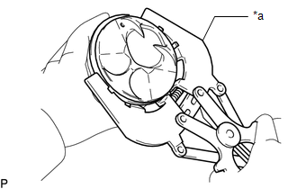
(a) Using a ridge reamer, remove all the carbon from the top of the cylinder. Text in Illustration
|
|
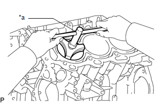
(b) Push the piston, connecting rod assembly and upper bearing through the top of the cylinder block.
HINT:
- Keep the bearing, connecting rod and cap together.
- Arrange the piston and connecting rod assemblies in the correct order.
4. REMOVE CONNECTING ROD BEARING
(a) Remove the connecting rod bearings from the connecting rods and connecting rod caps.
HINT:
Arrange the removed parts in the correct order.
5. REMOVE CRANKSHAFT
|
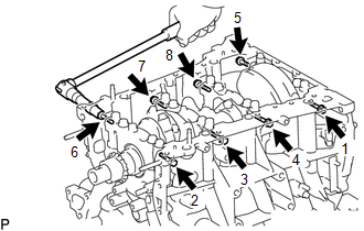
(a) Uniformly loosen and remove the 8 crankshaft bearing cap bolts and 8 seal washers in several steps and in the sequence shown in the illustration. |
|
|
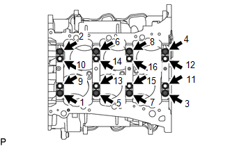
(b) Uniformly loosen the 16 crankshaft bearing cap bolts in several steps and in the sequence shown in the illustration. |
|
|
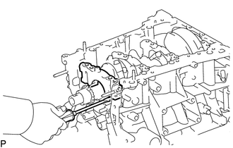
(c) Using a screwdriver, pry out the crankshaft bearing caps. Remove the 4 crankshaft bearing caps and lower crankshaft bearings. NOTICE:
|
|
(d) Remove the crankshaft.
6. REMOVE CRANKSHAFT BEARING
(a) Remove the upper crankshaft bearings and lower crankshaft bearings.
HINT:
Arrange the removed parts in the correct order.
7. REMOVE CRANKSHAFT THRUST WASHER SET
|
(a) Remove the upper crankshaft thrust washers from the cylinder block sub-assembly. |
|
8. REMOVE PISTON RING SET
|
(a) Using a piston ring expander, remove the 2 compression rings. Text in Illustration
|
|
(b) Remove the oil ring expander and 2 side rails by hand.
HINT:
Arrange the removed parts in the correct order.
9. REMOVE PISTON SUB-ASSEMBLY WITH PIN
(a) Disconnect the connecting rod from the piston.
|
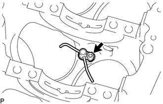
(1) Using a screwdriver, pry off the piston pin hole snap rings from the piston. |
|
(2) Gradually heat the piston to approximately 80°C (176°F).
|
(3) Using a brass bar and a plastic-faced hammer, lightly tap out the piston pin and remove the connecting rod sub-assembly. HINT:
|
|
(b) Using a gasket scraper, remove the carbon from the piston top.
(c) Using a groove cleaning tool or broken ring, clean the piston ring grooves.
(d) Using solvent and a brush, thoroughly clean the piston.
NOTICE:
Do not use a wire brush.
10. REMOVE NO. 1 OIL NOZZLE SUB-ASSEMBLY
|
(a) Using a 5 mm hexagon wrench, remove the 3 bolts and No. 1 oil nozzle sub-assemblies. |
|
(b) Check the 3 No. 1 oil nozzles for damage or clogging.
If necessary, replace the No. 1 oil nozzle sub-assembly.
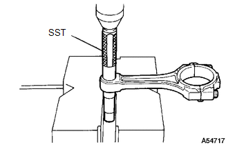
11. REMOVE CONNECTING ROD SMALL END BUSH
|
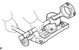
(a) Using SST and a press, press out the bush. SST: 09222-30010 |
|
 Precaution
PRECAUTION
HINT:
Any digits beyond the 0.01 mm (1/1000 in.) place for standard, minimum
and maximum values should be used as a reference only.
When both standard and maximum or minim ...
 Inspection
INSPECTION
PROCEDURE
1. INSPECT CYLINDER BLOCK FOR WARPAGE
(a) Using a precision straightedge and feeler gauge, measure the warpage
of the contact surface of the cylinder head gasket ...
Other materials:
Back window (vehicles with sliding type)
The back window can be opened and closed using the lock release lever.
Open/close
Push the lock release lever and slide the back window.
■Closing the back window
Make sure that the back window is securely closed after closing it.
CAUTION
■While driving
Keep the back window close ...
Front Radar Sensor (C1A10)
DESCRIPTION
C1A10 is output when there is an internal malfunction in the millimeter wave
radar sensor assembly.
DTC No.
Detection Item
DTC Detection Condition
Trouble Area
MIL
C1A10
Front Radar Sensor
W ...
System Diagram
SYSTEM DIAGRAM
Transmitting ECU (Transmitter)
Receiving ECU
Signal
Communication Method
4 wheel drive control ECU
Skid control ECU (Brake actuator assembly)
High-Low actuator fail
4WD status ...
