Toyota Tacoma (2015-2018) Service Manual: Components
COMPONENTS
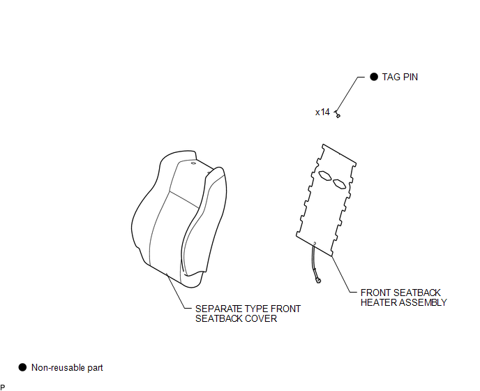
ILLUSTRATION

 Removal
REMOVAL
PROCEDURE
1. REMOVE FRONT SEAT ASSEMBLY (for Driver Side)
(See page
)
2. REMOVE FRONT SEAT ASSEMBLY (for Front Passenger Side)
(See page
)
3. REMOVE SEPARATE TYPE FRONT SEATBACK ...
Other materials:
Extension Housing Rear Oil Seal
Components
COMPONENTS
ILLUSTRATION
Replacement
REPLACEMENT
PROCEDURE
1. REMOVE PROPELLER SHAFT WITH CENTER BEARING ASSEMBLY
(See page )
2. REMOVE AUTOMATIC TRANSMISSION EXTENSION HOUSING OIL SEAL
(a) Using SST, remove the automatic transmission extension housing oil
se ...
Inspection
INSPECTION
PROCEDURE
1. INSPECT AIR CONDITIONING CONTROL ASSEMBLY
(a) Check the blower switch resistance.
(1) Measure the resistance according to the value(s) in the table below.
Text in Illustration
*a
Component without harness connected
...
Reassembly
REASSEMBLY
PROCEDURE
1. INSTALL FRONT LOWER ARM BUSH NO. 1
(a) Install a new lower arm bush using SST, a press and steel plate.
SST: 09631-12090
SST: 09631-32020
NOTICE:
Push the lower arm bush in until the bush positioning protrusions come to the
positions shown in the illustration.
2. ...
