
Toyota Tacoma (2015-2018) Service Manual: Removal
REMOVAL
PROCEDURE
1. REMOVE FRONT SEAT ASSEMBLY (for Driver Side)
(See page .gif) )
)
2. REMOVE FRONT SEAT ASSEMBLY (for Front Passenger Side)
(See page
)
3. REMOVE SEPARATE TYPE FRONT SEATBACK COVER (for Driver Side)
(See page
)
4. REMOVE SEPARATE TYPE FRONT SEATBACK COVER (for Front Passenger Side)
(See page
)
5. REMOVE FRONT SEATBACK HEATER ASSEMBLY
|
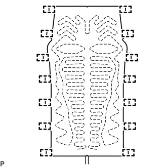
(a) Cut off the 14 tag pins which fasten the front seatback heater assembly to the front seatback cover, and then remove the front seatback heater assembly from the front seatback cover. |
|
 Components
COMPONENTS
ILLUSTRATION
...
 Inspection
INSPECTION
PROCEDURE
1. INSPECT FRONT SEATBACK HEATER ASSEMBLY
(a) Check the operation of the front seatback heater assembly.
(1) Apply battery voltage and check the operation of the ...
Other materials:
Check Bus 2 Line for Short to +B
DESCRIPTION
There may be a short circuit between one of the CAN bus lines and +B when no
resistance exists between terminal 18 (CA4H) of the central gateway ECU (network
gateway ECU) and terminal 16 (BAT) of the DLC3, or terminal 17 (CA4L) of the central
gateway ECU (network gateway ECU) and ...
Air Mix Damper Control Servo Motor Circuit (Driver Side) (B1446/46)
DESCRIPTION
This No. 3 air conditioning radiator damper servo sub-assembly (for driver side
air mix) is controlled by the air conditioning amplifier assembly and moves the
air mix damper (for driver side) to the desired position.
DTC No.
DTC Detection Condition
...
Lost Communication with Power Source Control (B278C)
DESCRIPTION
DTC No.
DTC Detection Condition
Trouble Area
B278C
An internal malfunction occurs in the certification ECU (smart key ECU
assembly)
Certification ECU (smart key ECU assembly)
CAUTI ...
