Toyota Tacoma (2015-2018) Service Manual: Removal
REMOVAL
PROCEDURE
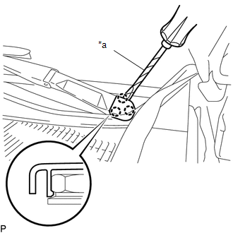
1. REMOVE FRONT WIPER ARM HEAD CAP
|
(a) Using a screwdriver with its tip wrapped in protective tape, disengage the 3 claws to remove the front wiper arm head cap. Text in Illustration
HINT: Use the same procedure for both sides. |
|
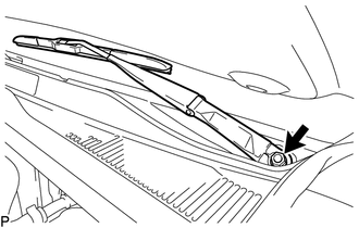
2. REMOVE WINDSHIELD WIPER ARM AND BLADE ASSEMBLY LH
|
(a) Remove the nut and windshield wiper arm and blade assembly LH. |
|
3. REMOVE WINDSHIELD WIPER ARM AND BLADE ASSEMBLY RH
HINT:
Use the same procedure as for the LH side.
4. REMOVE FRONT FENDER UPPER PROTECTOR LH
|
(a) Remove the clip. |
|
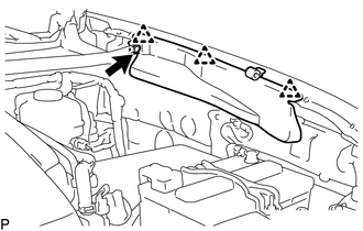
(b) Disengage the 3 clips to remove the front fender upper protector LH.
5. REMOVE FRONT FENDER UPPER PROTECTOR RH
HINT:
Use the same procedure as for the LH side.
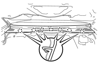
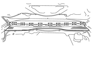
6. REMOVE COWL TOP VENTILATOR LOUVER SUB-ASSEMBLY
|
(a) Disengage the 6 claws and guide. |
|
|
(b) Disengage the 9 guides to remove the cowl top ventilator louver sub-assembly. |
|
7. REMOVE WINDSHIELD WIPER MOTOR AND LINK
|
(a) Disconnect the connector. Text in Illustration
|
|
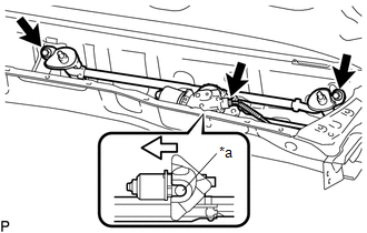
(b) Remove the 2 bolts.
(c) Disengage the motor grommet as shown in the illustration to remove the windshield wiper motor and link.
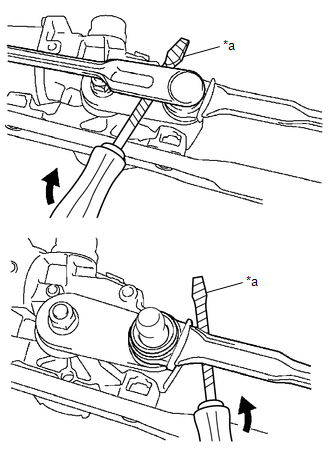
8. REMOVE WINDSHIELD WIPER MOTOR ASSEMBLY
|
(a) Using a screwdriver with its tip wrapped in protective tape, disengage the 2 rods at the crank arm pivot of the windshield wiper motor assembly. Text in Illustration
|
|
|
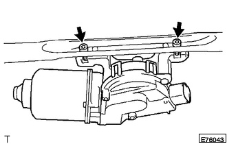
(b) Using a T30 "TORX" socket wrench, remove the 2 bolts and windshield wiper motor assembly. |
|
 Installation
INSTALLATION
PROCEDURE
1. INSTALL WINDSHIELD WIPER MOTOR ASSEMBLY
(a) Apply MP grease to the crank arm pivot of the windshield wiper motor
assembly.
Text in Illustration
...
 Front Wiper Rubber
Components
COMPONENTS
ILLUSTRATION
Installation
INSTALLATION
PROCEDURE
1. INSTALL FRONT WIPER RUBBER
(a) Install the 2 wiper rubber backing plates to the front wiper rubber.
...
Other materials:
Fuel information
Your vehicle must use only unleaded gasoline.
Select octane rating 87 (Research Octane Number 91) or higher. Use of unleaded
gasoline with an octane rating lower than 87 may result in engine knocking. Persistent
knocking can lead to engine damage.
At minimum, the gasoline you use should meet t ...
Installation
INSTALLATION
PROCEDURE
1. INSTALL VANE PUMP
(a) Install the vane pump assembly with the 2 bolts.
Torque:
21 N·m {214 kgf·cm, 15 ft·lbf}
(b) Connect the oil pressure switch connector.
NOTICE:
Make sure that no oil adheres to the connector.
...
Removal
REMOVAL
PROCEDURE
1. REMOVE RADIATOR GRILLE
(a) w/ Toyota Safety Sense P
(1) Disconnect the connector.
(2) Disengage the clamp.
(b) Put protective tape around the radiator grille.
...
