Toyota Tacoma (2015-2018) Service Manual: Reassembly
REASSEMBLY
CAUTION / NOTICE / HINT
HINT:
- Use the same procedures for both the LH and RH sides.
- The procedure described below is for the LH side.
PROCEDURE
1. INSTALL SIDE TURN SIGNAL LIGHT ASSEMBLY (w/ Side Turn Signal Light)
.gif)
2. INSTALL OUTER MIRROR COVER (w/o Side Turn Signal Light)
|
(a) Engage the 8 claws to install the outer mirror cover. |
|
.png)
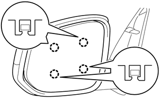
3. INSTALL OUTER MIRROR COVER (w/ Side Turn Signal Light)
|
(a) Engage the 7 claws to install the outer mirror cover. |
|
.png)
4. INSTALL OUTER MIRROR
|
(a) Connect the 3 connectors. |
|
.png)
(b) Engage the clamp.
|
(c) Engage the 4 claws to install the outer mirror. NOTICE: Be careful not to press the outer mirror with excessive force to prevent the glass from breaking. |
|
 Inspection
INSPECTION
PROCEDURE
1. INSPECT OUTER MIRROR LH
(a) Check the outer mirror heater operation.
Text in Illustration
*a
Component without harness con ...
 Installation
INSTALLATION
CAUTION / NOTICE / HINT
HINT:
Use the same procedures for both the LH and RH sides.
The procedure described below is for the LH side.
PROCEDURE
1. INSTALL OUTER REA ...
Other materials:
Tire Pressure Warning Light Circuit
DESCRIPTION
If the tire pressure warning ECU and receiver detects any problems, the tire
pressure warning light blinks for 1 minute then illuminates, and tire pressure monitoring
is disabled at the same time. At this time, the ECU stores a DTC in memory.
Connecting terminals TC and CG of the D ...
Precaution
PRECAUTION
PRECAUTION FOR DISCONNECTING CABLE FROM NEGATIVE BATTERY TERMINAL
NOTICE:
When disconnecting the cable from the negative (-) battery terminal,
initialize the following systems after the cable is reconnected.
Click here
If the battery has been discharged and char ...
Diagnostic Trouble Code Chart
DIAGNOSTIC TROUBLE CODE CHART
Navigation System
DTC Code
Detection Item
See page
B1324
Lost Communication with Meter
B1532
LVDS Signal Malfunction (from Extension Module)
...
