Toyota Tacoma (2015-2018) Service Manual: Clearance Warning Buzzer
Components
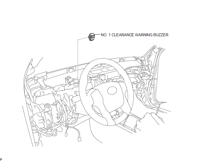
COMPONENTS
ILLUSTRATION
Installation
INSTALLATION
PROCEDURE
1. INSTALL NO. 1 CLEARANCE WARNING BUZZER
(a) Connect the connector.
(b) Engage the clamp to install the No. 1 clearance warning buzzer.
2. INSTALL INSTRUMENT PANEL SUB-ASSEMBLY
(See page .gif) )
)
Removal
REMOVAL
PROCEDURE
1. REMOVE INSTRUMENT PANEL SUB-ASSEMBLY
(See page .gif) )
)
2. REMOVE NO. 1 CLEARANCE WARNING BUZZER
|
(a) Disengage the clamp. |
|
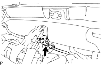
(b) Disconnect the connector to remove the No. 1 clearance warning buzzer.
 Clearance Sonar Main Switch
Components
COMPONENTS
ILLUSTRATION
Removal
REMOVAL
PROCEDURE
1. REMOVE INSTRUMENT PANEL LOWER CENTER FINISH PANEL
(See page )
2. REMOVE BACK SONAR OR CLEARANCE SONAR SWITCH ASSEMBLY
...
 Clearance Warning Ecu
Components
COMPONENTS
ILLUSTRATION
Installation
INSTALLATION
PROCEDURE
1. INSTALL CLEARANCE WARNING ECU ASSEMBLY
(a) Connect the connector.
(b) Engage the 2 guides to install the clearan ...
Other materials:
Components
COMPONENTS
ILLUSTRATION
*A
w/o Navigation System
*B
w/ Navigation System
*C
for Double Cab
*D
for Acces Cab
*E
for 4WD
-
-
*1
...
Data List / Active Test
DATA LIST / ACTIVE TEST
1. DATA LIST
HINT:
Using the Techstream to read the Data List allows the values or states of switches,
sensors, actuators and other items to be read without removing any parts. This non-intrusive
inspection can be very useful because intermittent conditions or signals ...
Check For Intermittent Problems
CHECK FOR INTERMITTENT PROBLEMS
1. DESCRIPTION
HINT:
A momentary interruption (open circuit) in the connectors and/or wire harness
between the sensors and ECUs can be detected through the ECU data monitor function
of the Techstream.
(a) Turn the ignition switch off.
(b) Connect the Techstre ...
