Toyota Tacoma (2015-2018) Service Manual: Clearance Sonar Main Switch
Components
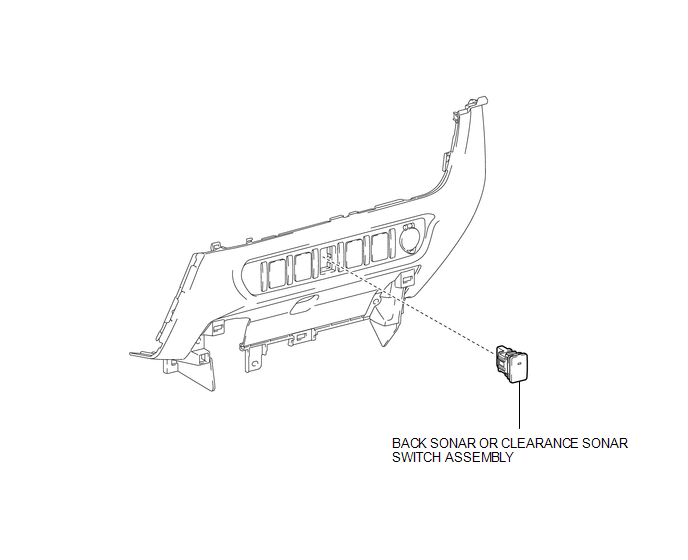
COMPONENTS
ILLUSTRATION
Removal
REMOVAL
PROCEDURE
1. REMOVE INSTRUMENT PANEL LOWER CENTER FINISH PANEL
(See page .gif) )
)
2. REMOVE BACK SONAR OR CLEARANCE SONAR SWITCH ASSEMBLY
|
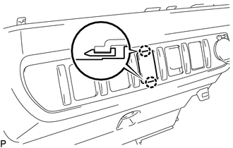
(a) Disengage the 2 claws to remove the back sonar or clearance sonar switch assembly. |
|
Inspection
INSPECTION
PROCEDURE
1. INSPECT BACK SONAR OR CLEARANCE SONAR SWITCH ASSEMBLY
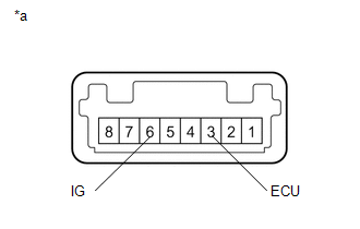
(a) Check the resistance.
|
(1) Measure the resistance according to the value(s) in the table below. Text in Illustration
Standard Resistance:
If the result is not as specified, replace the back sonar or clearance sonar switch assembly. |
|
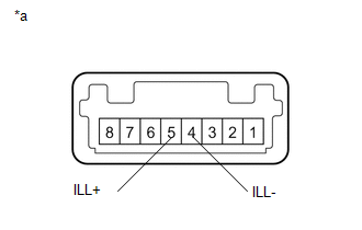
(b) Check the illumination operation.
|
(1) Apply battery voltage to the back sonar or clearance sonar switch assembly and check that the switch illuminates. Text in Illustration
If the result is not as specified, replace the back sonar or clearance sonar switch assembly. |
|
Installation
INSTALLATION
PROCEDURE
1. INSTALL BACK SONAR OR CLEARANCE SONAR SWITCH ASSEMBLY
(a) Engage the 2 claws to install the back sonar or clearance sonar switch assembly.
2. INSTALL INSTRUMENT PANEL LOWER CENTER FINISH PANEL
(See page .gif) )
)
 Power Source Circuit
DESCRIPTION
This circuit provides power to operate the blind spot monitor sensor.
WIRING DIAGRAM
CAUTION / NOTICE / HINT
NOTICE:
Inspect the fuses for circuits related to this system before per ...
 Clearance Warning Buzzer
Components
COMPONENTS
ILLUSTRATION
Installation
INSTALLATION
PROCEDURE
1. INSTALL NO. 1 CLEARANCE WARNING BUZZER
(a) Connect the connector.
(b) Engage the clamp to install the No. 1 clea ...
Other materials:
Rear Seat Inner Belt Assembly(for Double Cab)
Installation
INSTALLATION
PROCEDURE
1. INSTALL REAR SEAT INNER BELT ASSEMBLY
(a) for LH Side:
(1) Install the rear seat inner belt assembly with the bolt.
Text in Illustration
*a
Protruding Part
*b
...
Head restraints
Head restraints are provided for all seats.
■ Adjusting the head restraints
Bench type front seat
Up
Pull the head restraints up.
Down
Push the head restraint down while pushing the lock release button.
Separated type front seat
Up
Pull the head restraints up.
Down
Push th ...
Automatic Disconnecting Differential Motor Limit Switch Circuit (P17A4)
DESCRIPTION
When the A.D.D. actuator switches between 2WD and 4WD, the DL1 and DL2 terminals
of the limit switch and ADD terminal of the A.D.D. position switch change to one
of the following ON/OFF combinations listed in the table below.
Terminal
In 2WD
Switchi ...
