Toyota Tacoma (2015-2018) Service Manual: System Diagram
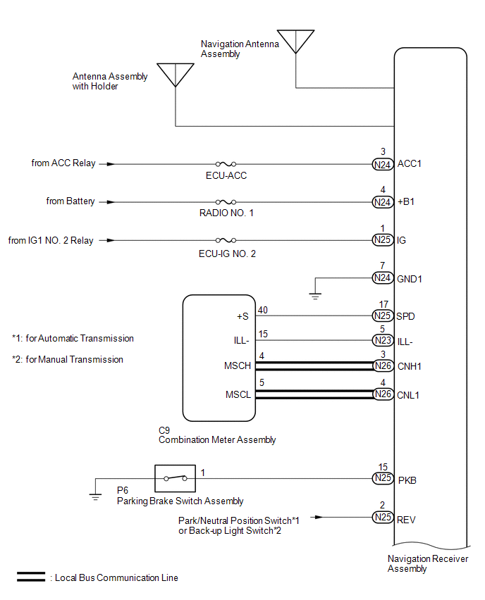
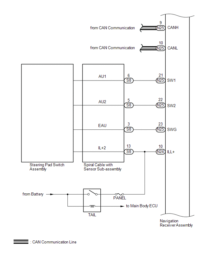
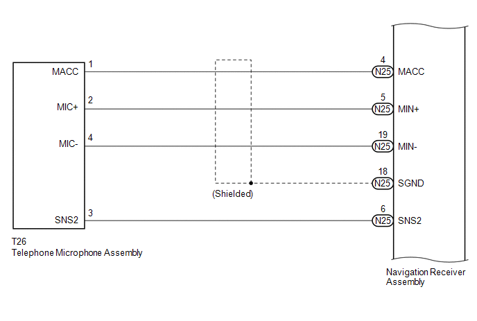
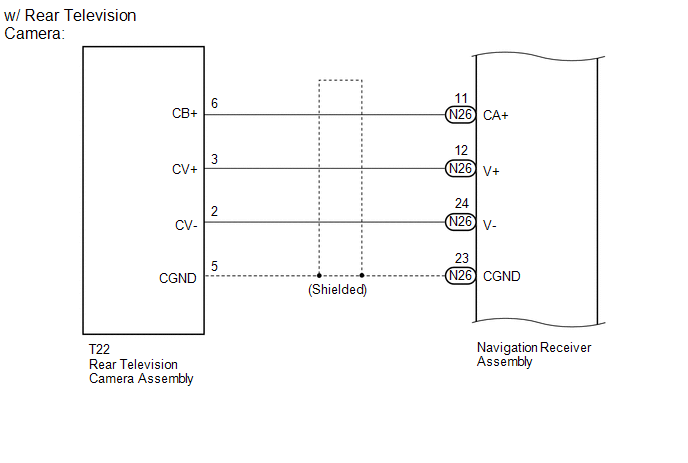
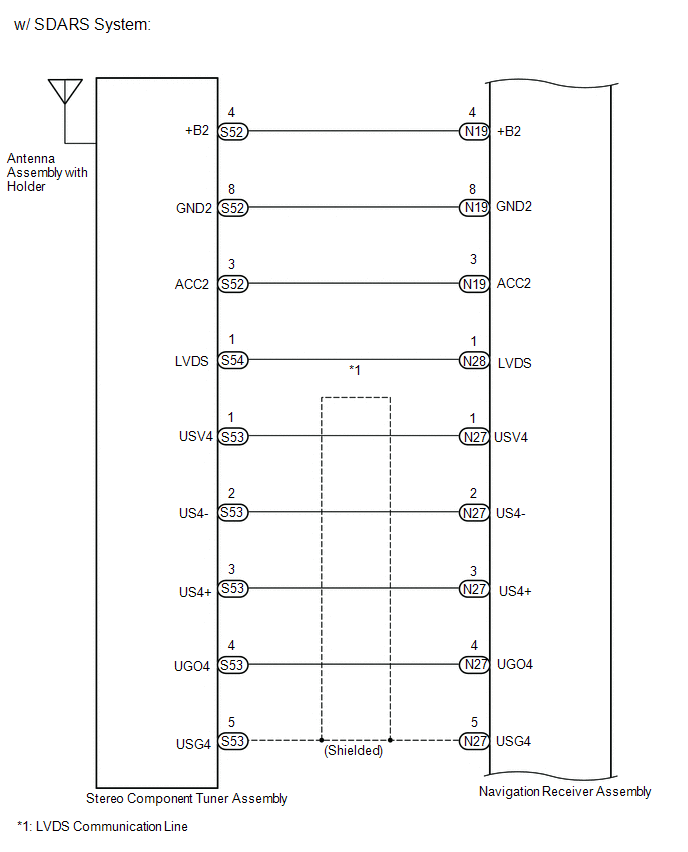
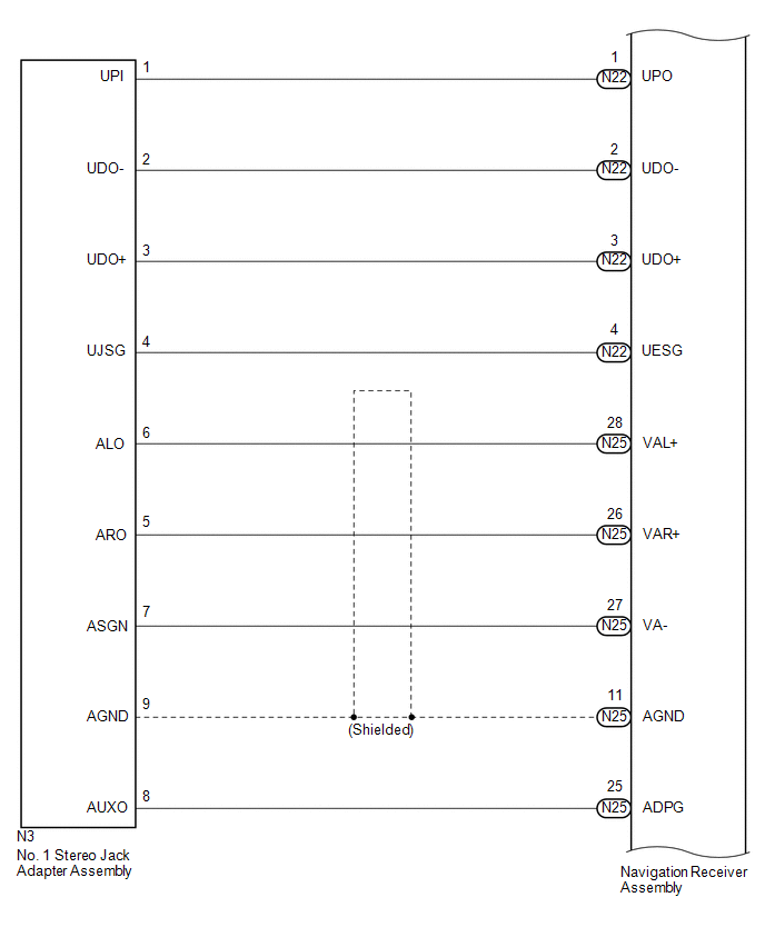
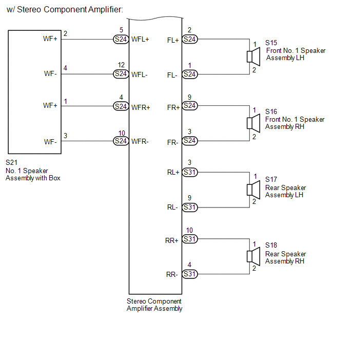
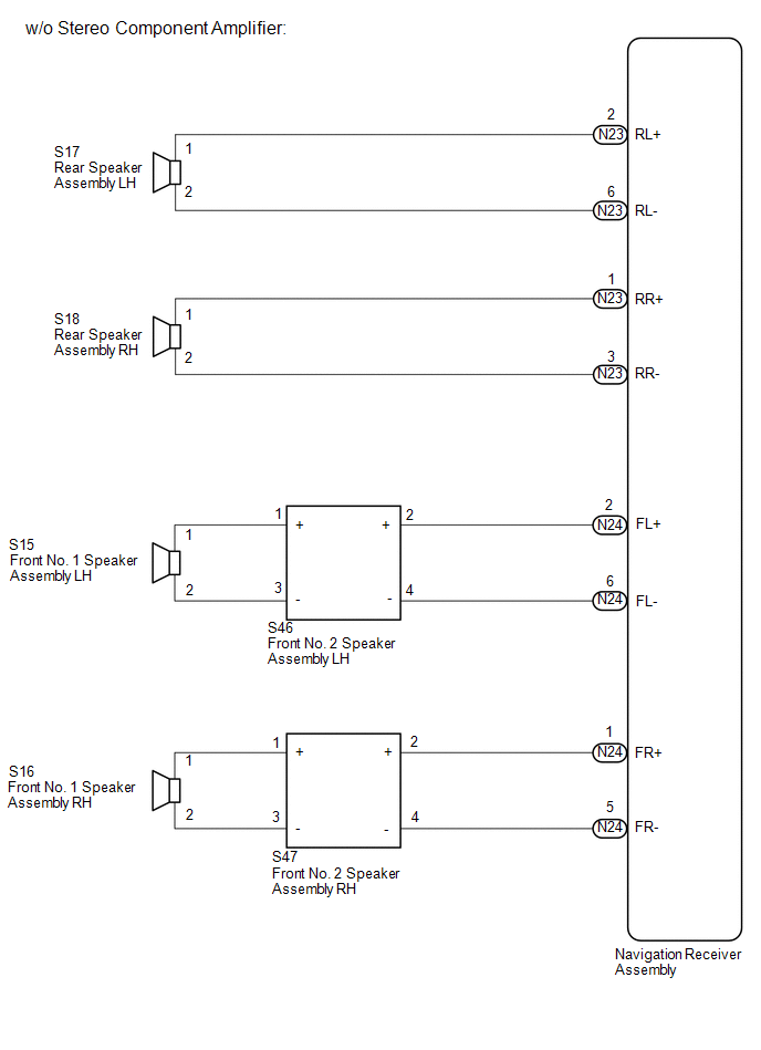
SYSTEM DIAGRAM

 Parts Location
PARTS LOCATION
ILLUSTRATION
ILLUSTRATION
ILLUSTRATION
ILLUSTRATION
...
 System Description
SYSTEM DESCRIPTION
1. NAVIGATION SYSTEM OUTLINE
(a) Vehicle position tracking methods
It is essential that the navigation system correctly tracks the current vehicle
position and displays it on t ...
Other materials:
Terminals Of Ecu
TERMINALS OF ECU
CHECK ECM
HINT:
The standard voltage, resistance and waveform between each pair of the ECM terminals
is shown in the table below. The appropriate conditions for checking each pair of
the terminals is also indicated. The result of checks should be compared with the
standar ...
Data List / Active Test
DATA LIST / ACTIVE TEST
1. DATA LIST
NOTICE:
In the table below, the values listed under "Normal Condition" are reference
values. Do not depend solely on these reference values when deciding whether a part
is faulty or not.
HINT:
Using the Techstream to read the Data List allows t ...
Pressure Control Solenoid "D" Circuit Open (P271313)
DESCRIPTION
Refer to the system description for DTC P27137F (See page
).
DTC No.
DTC Detection Condition
Trouble Area
SAE
P271313
Open or short is detected in shift solenoid valve SLT circuit for 1 second
or more while d ...
