Toyota Tacoma (2015-2018) Service Manual: Power Source Circuit
DESCRIPTION
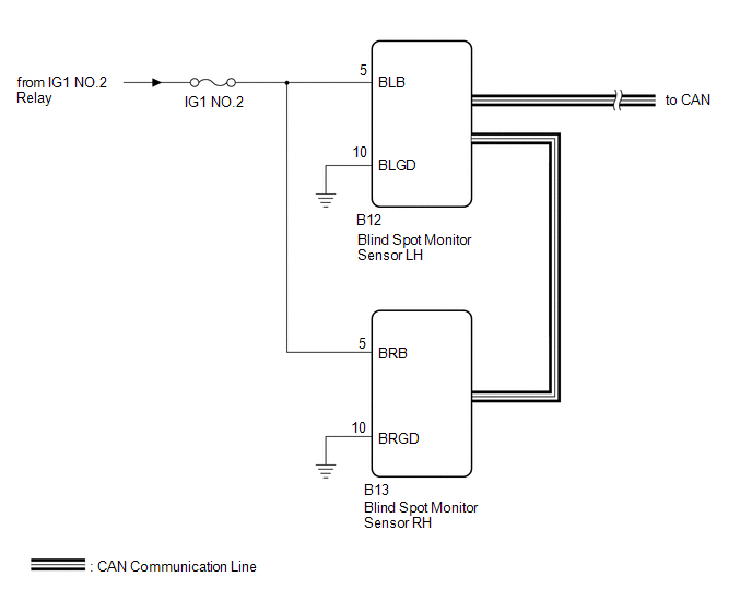
This circuit provides power to operate the blind spot monitor sensor.
WIRING DIAGRAM
CAUTION / NOTICE / HINT
NOTICE:
Inspect the fuses for circuits related to this system before performing the following inspection procedure.
PROCEDURE
|
1. |
CHECK HARNESS AND CONNECTOR (BLIND SPOT MONITOR SENSOR RH, BLIND SPOT MONITOR SENSOR LH - BATTERY AND BODY GROUND) |
|
(a) Disconnect the blind spot monitor sensor LH connector. |
|
(b) Disconnect the blind spot monitor sensor RH connector.
(c) Measure the voltage according to the value(s) in the table below.
Standard Voltage:
|
Tester Connection |
Switch Condition |
Specified Condition |
|---|---|---|
|
B12-5 (BLB) - Body ground |
Ignition switch ON |
11 to 14 V |
|
B12-5 (BLB) - Body ground |
Ignition switch off |
Below 1 V |
|
B13-5 (BRB) - Body ground |
Ignition switch ON |
11 to 14 V |
|
B13-5 (BRB) - Body ground |
Ignition switch off |
Below 1 V |
(d) Measure the resistance according to the value(s) in the table below.
Standard Resistance:
|
Tester Connection |
Condition |
Specified Condition |
|---|---|---|
|
B12-10 (BLGD) - Body ground |
Always |
Below 1 Ω |
|
B13-10 (BRGD) - Body ground |
Always |
Below 1 Ω |
|
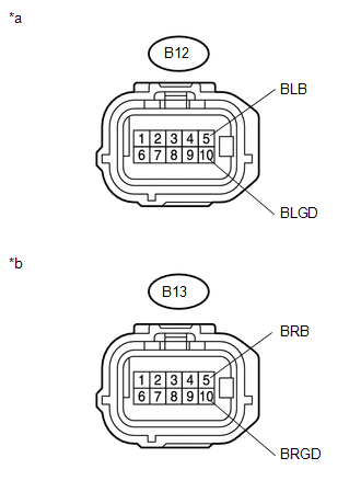
*a |
Front view of wire harness connector (to Blind Spot Monitor Sensor LH) |
|
*b |
Front view of wire harness connector (to Blind Spot Monitor Sensor RH) |
| OK | .gif) |
PROCEED TO NEXT SUSPECTED AREA SHOWN IN PROBLEM SYMPTOMS TABLE |
| NG | |
REPAIR OR REPLACE HARNESS OR CONNECTOR |
 Main Switch Circuit
DESCRIPTION
When the blind spot monitor main switch assembly (warning canceling switch assembly)
is turned on, a signal is sent to the blind spot monitor sensor LH. The blind spot
monitor system ...
 Clearance Sonar Main Switch
Components
COMPONENTS
ILLUSTRATION
Removal
REMOVAL
PROCEDURE
1. REMOVE INSTRUMENT PANEL LOWER CENTER FINISH PANEL
(See page )
2. REMOVE BACK SONAR OR CLEARANCE SONAR SWITCH ASSEMBLY
...
Other materials:
Front Right Seat Heat Sensor Circuit (B14C0)
DESCRIPTION
Output to the front seat cushion heater assembly RH temperature sensor stops
if one of the following occurs: 1) the temperature sensor is open or shorted; or
2) the temperature sensor is damaged and its output value does not change.
DTC Code
DTC Detection Cond ...
Operation Check
OPERATION CHECK
1. INSPECT INTERIOR LIGHT CONTROL OPERATION
NOTICE:
Perform this inspection with the customize parameters at the default settings.
The interior light control illuminates the lights below.
Engine Switch Illumination*1
Transponder Key Coil (Ignition Key Cylinder Light)* ...
Terminals Of Ecu
TERMINALS OF ECU
1. CHECK CERTIFICATION ECU (SMART KEY ECU ASSEMBLY)
(a) Disconnect the C27 and C29 certification ECU (smart key ECU assembly) connectors.
(b) Measure the voltage and resistance according to the value(s) in the table
below.
HINT:
Measure the values on the wire harness side w ...
