Toyota Tacoma (2015-2018) Service Manual: Cargo Light
Components
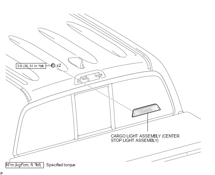
COMPONENTS
ILLUSTRATION
Removal
REMOVAL
PROCEDURE
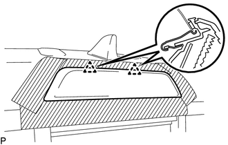
1. REMOVE ROOF HEADLINING ASSEMBLY
- for Double Cab:
(See page
.gif) )
) - for Access Cab:
(See page
)
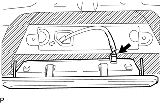
2. REMOVE CARGO LIGHT ASSEMBLY (CENTER STOP LIGHT ASSEMBLY)
|
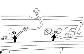
(a) Remove the 2 nuts. |
|
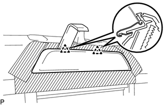
(b) Apply protective tape around the cargo light assembly (center stop light assembly).
 Text in Illustration
.png) |
Protective Tape |
|
(c) Using a moulding remover D, disengage the 2 clips to separate the cargo light assembly (center stop light assembly). |
|
|
(d) Disconnect the connector to remove the cargo light assembly (center stop light assembly). |
|
Inspection
INSPECTION
PROCEDURE
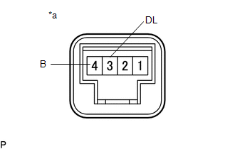
1. INSPECT CARGO LIGHT ASSEMBLY (CENTER STOP LIGHT ASSEMBLY)
(a) Check the illuminates.
|
(1) Apply battery voltage to the connector and check the light illumination condition. Text in Illustration
OK:
If the result is not as specified, replace the cargo light assembly (center stop light assembly). |
|
Installation
INSTALLATION
PROCEDURE
1. INSTALL CARGO LIGHT ASSEMBLY (CENTER STOP LIGHT ASSEMBLY)
(a) Connect the connector.
|
(b) Engage the 2 clips to install the cargo light assembly (center stop light assembly). |
|
(c) Install the 2 nuts.
Torque:
3.6 N·m {36 kgf·cm, 31 in·lbf}
(d) Remove the protective tape.
2. INSPECT ROOF HEADLINING ASSEMBLY
- for Double Cab:
(See page
.gif) )
) - for Access Cab:
(See page
)
 Automatic Light Control Sensor
Components
COMPONENTS
ILLUSTRATION
Installation
INSTALLATION
PROCEDURE
1. INSTALL AUTOMATIC LIGHT CONTROL SENSOR
(a) Engage the 2 claws to install the automatic light control sensor.
2. ...
 Cargo Light Switch
Components
COMPONENTS
ILLUSTRATION
Inspection
INSPECTION
PROCEDURE
1. INSPECT DECK LIGHT SWITCH ASSEMBLY
(a) Check the resistance.
(1) Measure the resistance according to the ...
Other materials:
Removal
REMOVAL
CAUTION / NOTICE / HINT
CAUTION:
Some of these service operations affect the SRS airbag system. Read
the precautionary notices concerning the SRS airbag system before servicing
(See page ).
If the side airbag was deployed, replace the front seat assembly with
a ne ...
Freeze Frame Data
FREEZE FRAME DATA
1. CHECK FREEZE FRAME DATA
(a) Connect the Techstream to the DLC3.
(b) Turn the ignition switch to ON.
(c) Turn the Techstream on.
(d) Enter the following menus: Body Electrical / Navigation System / Trouble
Codes.
(e) Select a PTC to display its Freeze Frame Data.
2. LIST ...
Definition Of Terms
DEFINITION OF TERMS
Term
Definition
Monitor description
Description of what the ECM monitors and how it detects malfunctions
(monitoring purpose and details).
Related DTCs
Group of diagnostic trouble codes that are ou ...
