Toyota Tacoma (2015-2018) Service Manual: Cargo Light Switch
Components
COMPONENTS
ILLUSTRATION
Inspection
INSPECTION
PROCEDURE
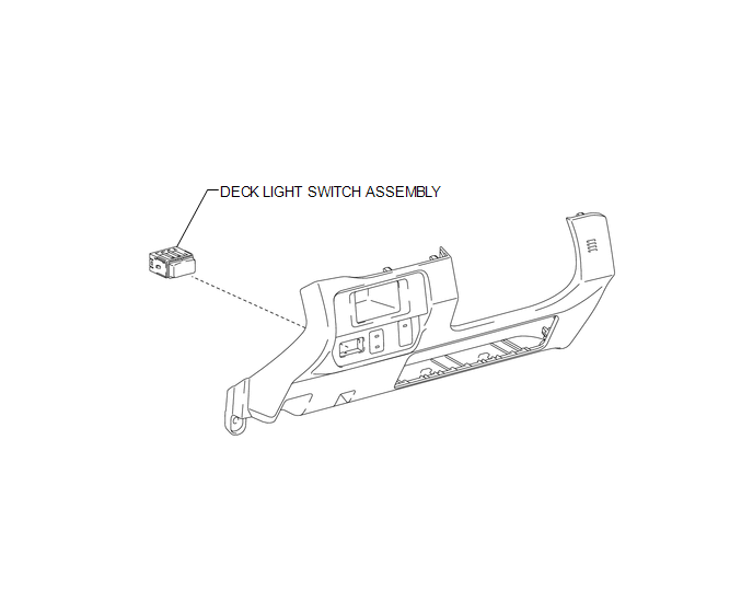
1. INSPECT DECK LIGHT SWITCH ASSEMBLY
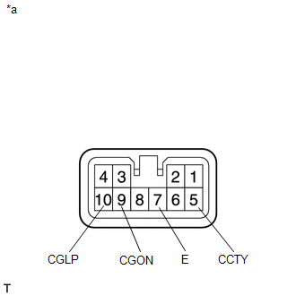
(a) Check the resistance.
|
(1) Measure the resistance according to the value(s) in the table below. Text in Illustration
Standard Resistance:
If the result is not as specified, replace the deck light switch assembly. |
|
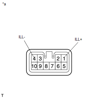
(b) Check the illumination.
|
(1) Apply battery voltage to the connector and check the illumination condition. Text in Illustration
OK:
If the result is not as specified, replace the deck light switch assembly. |
|
Installation
INSTALLATION
PROCEDURE
1. INSTALL DECK LIGHT SWITCH ASSEMBLY
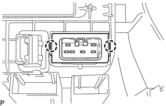
(a) Engage the 2 claws to install the deck light switch assembly.
2. INSTALL INSTRUMENT PANEL LOWER FINISH PANEL SUB-ASSEMBLY
(See page .gif) )
)
Removal
REMOVAL
PROCEDURE
1. REMOVE INSTRUMENT PANEL LOWER FINISH PANEL SUB-ASSEMBLY
(See page .gif) )
)
2. REMOVE DECK LIGHT SWITCH ASSEMBLY
|
(a) Disengage the 2 claws to remove the deck light switch assembly. |
|
 Cargo Light
Components
COMPONENTS
ILLUSTRATION
Removal
REMOVAL
PROCEDURE
1. REMOVE ROOF HEADLINING ASSEMBLY
for Double Cab:
(See page
)
for Access Cab:
(See page
)
...
 Daytime Running Light Relay
Inspection
INSPECTION
PROCEDURE
1. INSPECT NO. 1 DAY TIME RUNNING LIGHT RELAY
(a) Check the resistance.
(1) Measure the resistance according to the value(s) in the table below.
St ...
Other materials:
Check Bus 2 Lines for Short Circuit
DESCRIPTION
There may be a short circuit between the CAN main bus lines and/or CAN branch
lines when the resistance between terminals 18 (CA4H) and 17 (CA4L) of the central
gateway ECU (network gateway ECU) is below 54 Ω.
Detection Item
Trouble Area
Resi ...
Poor Sound Quality in All Modes (Low Volume)
PROCEDURE
1.
CHECK AUDIO SETTINGS
(a) Set "Treble", "Mid" and "Bass" to the initial values and check that sound
is normal.
OK:
Malfunction disappears.
HINT:
Sound quality adjustment measures vary according to the type of amplifie ...
Road Test
ROAD TEST
HINT:
'SET' and '-', 'RES' and '+', 'ON-OFF' functions share the same switch. Operate
the cruise control main switch according to the directions indicated on the switch.
1. INSPECT 'SET' FUNCTION
(a) Push the ON-OFF button on (A).
(b ...
