Toyota Tacoma (2015-2018) Service Manual: Automatic Light Control Sensor
Components
COMPONENTS
ILLUSTRATION
Installation
INSTALLATION
PROCEDURE
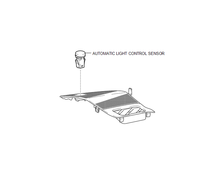
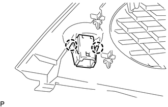
1. INSTALL AUTOMATIC LIGHT CONTROL SENSOR
(a) Engage the 2 claws to install the automatic light control sensor.
2. INSTALL NO. 2 INSTRUMENT PANEL SPEAKER PANEL SUB-ASSEMBLY
(See page .gif) )
)
On-vehicle Inspection
ON-VEHICLE INSPECTION
PROCEDURE
1. REMOVE NO. 2 INSTRUMENT PANEL SPEAKER PANEL SUB-ASSEMBLY
(See page .gif) )
)
2. INSPECT AUTOMATIC LIGHT CONTROL SENSOR
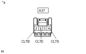
(a) Check the voltage.
|
(1) Measure the voltage according to the value(s) in the table below. Text in Illustration
Standard Voltage:
If the result is not as specified, repair or replace the wire harness. |
|
(2) Measure the resistance according to the value(s) in the table below.
Standard Resistance:
|
Tester Connection |
Condition |
Specified Condition |
|---|---|---|
|
A37-2 (CLTE) - Body ground |
Always |
Below 1 Ω |
If the result is not as specified, repair or replace the wire harness.
(b) Connect the connector.
|
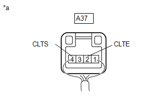
(c) Connect an oscilloscope to the automatic light control sensor connector. Text in Illustration
|
|
|
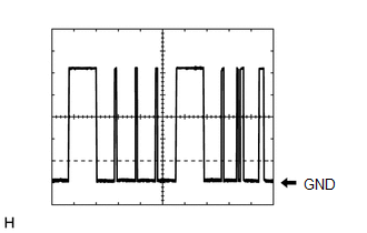
(d) Check the waveform. :
HINT: The communication waveform changes according to the surrounding brightness. If the result is not as specified, replace the automatic light control sensor. |
|
3. INSTALL NO. 2 INSTRUMENT PANEL SPEAKER PANEL SUB-ASSEMBLY
(See page )
Removal
REMOVAL
PROCEDURE
1. REMOVE NO. 2 INSTRUMENT PANEL SPEAKER PANEL SUB-ASSEMBLY
(See page .gif) )
)
2. REMOVE AUTOMATIC LIGHT CONTROL SENSOR
|
(a) Disengage the 2 claws to remove the automatic light control sensor. |
|
 Lighting
...
 Cargo Light
Components
COMPONENTS
ILLUSTRATION
Removal
REMOVAL
PROCEDURE
1. REMOVE ROOF HEADLINING ASSEMBLY
for Double Cab:
(See page
)
for Access Cab:
(See page
)
...
Other materials:
A/C ECU Vehicle Information Reading/Writing Processor Malfunction (B15F5)
DESCRIPTION
This DTC is stored when items controlled by the Air conditioning amplifier assembly
cannot be customized via the navigation system vehicle customization screen.
HINT:
The Air conditioning amplifier assembly controls the air conditioning system
related items that are customizable v ...
Indicator Circuit
DESCRIPTION
The forward recognition camera sends indicator illumination request signals to
the combination meter assembly via CAN communication.
CAUTION / NOTICE / HINT
NOTICE:
When replacing the combination meter assembly, always replace it with a new one.
If a combination meter assembly wh ...
Steering Lock Position Signal Circuit Malfunction (B2285)
DESCRIPTION
This DTC is stored when the steering lock position signal sent by the steering
lock ECU (steering lock actuator or upr bracket assembly) via direct line and the
steering lock position signal sent via LIN communication do not match.
HINT:
When the cable is disconnected and reconnec ...
