Toyota Tacoma (2015-2018) Service Manual: Camera Heater
Components
COMPONENTS
ILLUSTRATION
|
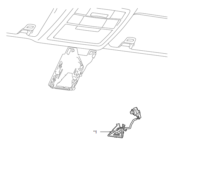
*1 |
FORWARD RECOGNITION WITH HEATER HOOD SUB-ASSEMBLY |
- |
- |
Removal
REMOVAL
PROCEDURE
1. REMOVE FORWARD RECOGNITION CAMERA
Click here .gif)
2. REMOVE FORWARD RECOGNITION WITH HEATER HOOD SUB-ASSEMBLY
NOTICE:
Do not touch the internal components of the forward recognition with heater hood sub-assembly or press on the heater when working on the forward recognition with heater hood sub-assembly.
|
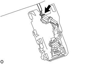
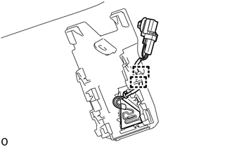
(a) Disconnect the connector. NOTICE: Do not pull the harness forcibly when disconnecting the connector. |
|
|
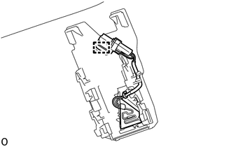
(b) Disengage the connector clamp. |
|
|
(c) Disengage the 2 guides to disconnect the wire harness. |
|
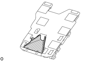
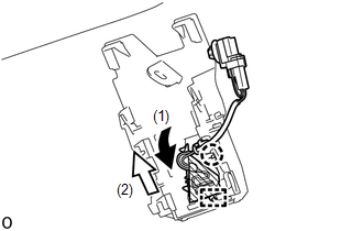
(d) Disengage the claw in the direction indicated by the arrow (1) in the illustration.
.png) |
Heater Area |
NOTICE:
Do not press the heater area.
(e) Disengage the guide in the direction indicated by the arrow (2) in the illustration to remove the forward recognition with heater hood sub-assembly.
Installation
INSTALLATION
PROCEDURE
1. INSTALL FORWARD RECOGNITION WITH HEATER HOOD SUB-ASSEMBLY
NOTICE:
Do not touch the internal components of the forward recognition with heater hood sub-assembly or press on the heater when working on the forward recognition with heater hood sub-assembly.
.png)
.png) |
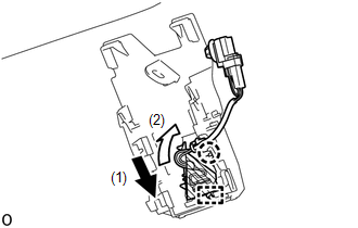
Heater Area |
(a) Engage the guide in the direction indicated by the arrow (1) in the illustration.
(b) Engage the claw in the direction indicated by the arrow (2) in the illustration.
NOTICE:
Do not press the heater area.
|
(c) Engage the 2 guides to connect the wire harness to the forward recognition bracket. |
|
.png)
|
(d) Engage the connector clamp to install the forward recognition with heater hood sub-assembly. |
|
.png)
|
(e) Connect the connector. |
|
.png)
2. INSTALL FORWARD RECOGNITION CAMERA
Click here .gif)
 Cruise Control
...
 Clutch Switch
Components
COMPONENTS
ILLUSTRATION
Removal
REMOVAL
PROCEDURE
1. PRECAUTION
NOTICE:
After turning the engine switch off, waiting time may be required before disconnecting
the cable from ...
Other materials:
Glossary Of Sae And Toyota Terms
GLOSSARY OF SAE AND TOYOTA TERMS
This glossary lists all SAE-J1930 terms and abbreviations used in this manual
in compliance with SAE recommendations, as well as their TOYOTA equivalents.
SAE ABBREVIATIONS
SAE TERMS
TOYOTA TERMS ( )-ABBREVIATIONS
...
Vehicle Speed Sensor "A" No Signal (P050031)
DESCRIPTION
The speed sensor detects the wheel speed and sends the appropriate signals to
the skid control ECU. The skid control ECU converts these wheel speed signals into
a pulse signal and outputs it to the ECM via the combination meter. The ECM determines
the vehicle speed based on the fr ...
Power Source Mode does not Change to ON (ACC)
DESCRIPTION
If the engine switch is pressed with the electrical key transmitter sub-assembly
in the cabin, the certification ECU (smart key ECU assembly) receives a signal and
changes the power source mode.
HINT:
When the cable is disconnected and reconnected to the negative (-) battery termi ...
