Toyota Tacoma (2015-2018) Service Manual: SRS Warning Light does not Come ON
DESCRIPTION
See page .gif) .
.
WIRING DIAGRAM
See page .
CAUTION / NOTICE / HINT
NOTICE:
- Inspect the fuses for circuits related to this system before performing the following inspection procedure.
- After turning the ignition switch off, waiting time may be required
before disconnecting the cable from the battery terminal. Therefore, make
sure to read the disconnecting the cable from the battery terminal notice
before proceeding with work (See page
).
PROCEDURE
|
1. |
INSPECT BATTERY |
(a) Measure the voltage of the battery.
Standard Voltage:
|
Tester Connection |
Condition |
Specified Condition |
|---|---|---|
|
Battery |
Always |
11 to 14 V |
| NG | .gif) |
CHECK AND REPLACE BATTERY OR CHARGING SYSTEM |
|
.gif)
|
2. |
CHECK CONNECTION OF CONNECTORS |
(a) Turn the ignition switch off.
(b) Disconnect the cable from the negative (-) battery terminal, and wait for at least 90 seconds.
(c) Check that the connectors are properly connected to the airbag sensor assembly and the combination meter assembly.
OK:
The connectors are properly connected.
| NG | |
CONNECT CONNECTORS PROPERLY |
|
|
3. |
CHECK HARNESS AND CONNECTOR (SOURCE VOLTAGE OF COMBINATION METER ASSEMBLY) |
|
(a) Turn the ignition switch off. |
|
(b) Disconnect the cable from the negative (-) battery terminal, and wait for at least 90 seconds.
(c) Disconnect the connectors from the combination meter assembly.
(d) Connect the cable to the negative battery terminal, and wait for at least 2 seconds.
(e) Turn the ignition switch to ON.
(f) Measure the voltage according to the value(s) in the table below.
Standard Voltage:
|
Tester Connection |
Switch Condition |
Specified Condition |
|---|---|---|
|
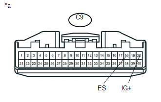
C9-20 (IG+) - C9-18 (ES) |
Ignition switch ON |
11 to 14 V |
|
*a |
Front view of wire harness connector (to Combination Meter Assembly) |
| NG | |
REPAIR OR REPLACE HARNESS OR CONNECTOR |
|
|
4. |
CHECK SRS WARNING LIGHT |
(a) Turn the ignition switch off.
(b) Disconnect the cable from the negative (-) battery terminal, and wait for at least 90 seconds.
(c) Connect the connector to the combination meter assembly.
(d) Connect the cable to the negative (-) battery terminal, and wait for at least 2 seconds.
(e) Turn the ignition switch to ON.
(f) Check the SRS warning light condition.
OK:
The SRS warning light turns off after the primary check period and comes on again after approximately 10 seconds.
HINT:
The primary check period lasts for approximately 6 seconds after the ignition switch is turned to ON.
| OK | |
REPLACE AIRBAG SENSOR ASSEMBLY |
| NG | |
REPLACE COMBINATION METER ASSEMBLY |
 Front Airbag Sensor RH Circuit Malfunction (B1610/13)
DESCRIPTION
The front airbag sensor RH consists of parts such as the diagnostic circuit and
the frontal detection sensor.
When the airbag sensor assembly receives signals from the frontal decelera ...
 SRS Warning Light Remains ON
DESCRIPTION
The SRS warning light is located on the combination meter assembly.
When the SRS condition is normal, the SRS warning light illuminates for approximately
6 seconds after the ignition s ...
Other materials:
Tire Pressure Warning Receiver
Components
COMPONENTS
ILLUSTRATION
Removal
REMOVAL
PROCEDURE
1. SEPARATE ROOF HEADLINING ASSEMBLY (for Double Cab)
(See page )
2. SEPARATE ROOF HEADLINING ASSEMBLY (for Access Cab)
(See page )
3. REMOVE TIRE PRESSURE WARNING ECU AND RECEIVER
(a) Disconnect the connector.
(b) ...
Problem Symptoms Table
PROBLEM SYMPTOMS TABLE
HINT:
Use the table below to help determine the cause of problem symptoms. If multiple
suspected areas are listed, the potential causes of the symptoms are listed in order
of probability in the "Suspected Area" column of the table. Check each symptom by
check ...
Acceleration Sensor Power Supply Voltage Malfunction (C1381)
DESCRIPTION
The skid control ECU (master cylinder solenoid) receives signals from the yaw
rate and acceleration (airbag sensor assembly) via the CAN communication system.
The airbag sensor assembly has a built-in yaw rate and acceleration sensor and
detects the vehicle's condition using 2 ...
