Toyota Tacoma (2015-2018) Service Manual: Fender Panel Mudguard
Components
COMPONENTS
ILLUSTRATION
ILLUSTRATION
Installation
INSTALLATION
CAUTION / NOTICE / HINT
HINT:
- Use the same procedure for the RH side and LH side.
- The following procedure is for the LH side.
PROCEDURE
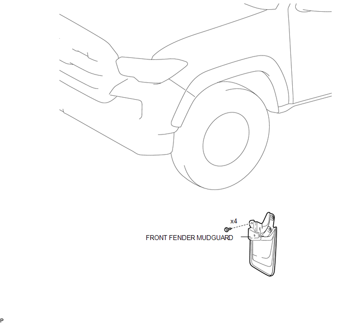
1. INSTALL FRONT FENDER MUDGUARD
(a) Install the front fender mudguard with the 4 screws.
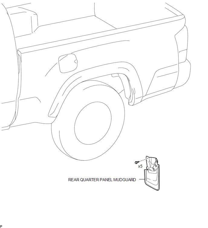
2. INSTALL REAR QUARTER PANEL MUDGUARD
(a) Install the rear quarter panel mudguard with the 5 screws.
Removal
REMOVAL
CAUTION / NOTICE / HINT
HINT:
- Use the same procedure for the RH side and LH side.
- The following procedure is for the LH side.
PROCEDURE
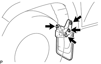
1. REMOVE FRONT FENDER MUDGUARD
|
(a) Remove the 4 screws and front fender mudguard. |
|
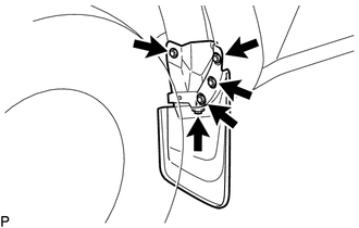
2. REMOVE REAR QUARTER PANEL MUDGUARD
|
(a) Remove the 5 screws and rear quarter panel mudguard. |
|
 Exterior
...
 Front Bumper
...
Other materials:
Coolant
Replacement
REPLACEMENT
PROCEDURE
1. REMOVE NO. 2 ENGINE UNDER COVER SUB-ASSEMBLY (w/ Off Road Package)
2. REMOVE NO. 1 ENGINE UNDER COVER SUB-ASSEMBLY
3. DRAIN ENGINE COOLANT
CAUTION:
Do not remove the radiator cap sub-assembly, cylinder block drain cock
plug or radiator drain ...
Front Passenger Side Seat Heater does not Operate
DESCRIPTION
When the seat heater switch on the air conditioning control assembly is operated,
the air conditioning amplifier assembly receives the signal. The air conditioning
amplifier assembly receives the signal and operates the front seat heater.
WIRING DIAGRAM
CAUTION / NOTICE / HINT
...
Problem Symptoms Table
PROBLEM SYMPTOMS TABLE
HINT:
Use the table below to help determine the cause of problem symptoms. If multiple
suspected areas are listed, the potential causes of the symptoms are listed in order
of probability in the "Suspected Area" column of the table. Check each symptom by
check ...
