Toyota Tacoma (2015-2018) Service Manual: Brake Warning Light Remains ON
DESCRIPTION
The BRAKE warning light comes on when brake fluid is insufficient, the parking brake is applied or the EBD is defective.
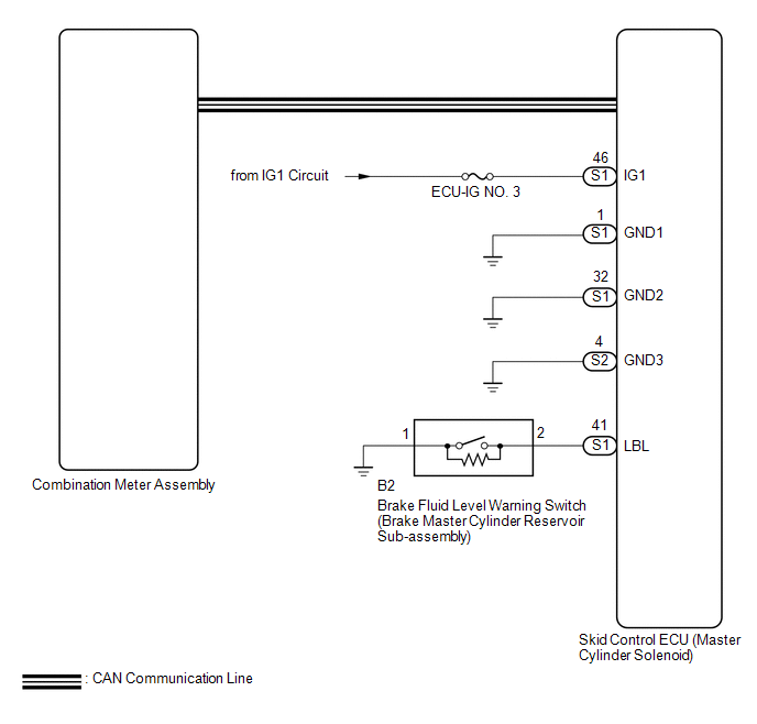
WIRING DIAGRAM
CAUTION / NOTICE / HINT
NOTICE:
- When replacing the skid control ECU (master cylinder solenoid), perform
calibration (See page
.gif) ).
). - Inspect the fuses for circuits related to this system before performing the following inspection procedure.
PROCEDURE
|
1. |
CHECK THAT SKID CONTROL ECU CONNECTOR SECURELY CONNECTED |
(a) Check the skid control ECU (master cylinder solenoid) connector connection.
OK:
The connector is securely connected.
| NG | .gif) |
CONNECT CONNECTOR TO ECU CORRECTLY |
|
.gif)
|
2. |
CHECK DTC |
(a) Check for DTCs (See page
).
|
Result |
Proceed to |
|---|---|
|
DTC is not output |
A |
|
DTC is output |
B |
| B | |
REPAIR CIRCUITS INDICATED BY OUTPUT DTCS |
|
|
3. |
INSPECT BATTERY |
(a) Inspect the battery voltage (See page ).
Standard voltage:
11 to 14 V
| NG | |
CHECK CHARGING SYSTEM |
|
|
4. |
CHECK BRAKE FLUID LEVEL |
(a) Turn the ignition switch off.
(b) Depress the brake pedal 20 times or more (until the pedal reaction feels light and pedal stroke becomes longer).
(c) Check the amount of fluid in the brake reservoir.
HINT:
When the ignition switch is turned to ON, brake fluid is sent to the accumulator and the fluid level decreases by approximately 5 mm (0.197 in.) from the level when the ignition switch is off (normal).
OK:
Brake fluid level is normal.
| NG | |
CHECK AND REPAIR BRAKE FLUID LEAKAGE |
|
|
5. |
CHECK CAN COMMUNICATION SYSTEM |
(a) Turn the ignition switch off.
(b) Connect the Techstream to the DLC3.
(c) Turn the ignition switch to ON.
(d) Turn the Techstream on.
(e) Select CAN Bus Check from the System Selection Menu screen and follow the
prompts on the screen to inspect the CAN bus (See page
).
OK:
CAN Bus Check indicates no malfunctions in CAN communication.
| NG | |
GO TO CAN COMMUNICATION SYSTEM (HOW TO PROCEED WITH TROUBLESHOOTING) |
|
|
6. |
PERFORM ACTIVE TEST USING TECHSTREAM (BRAKE WARNING LIGHT) |
(a) Turn the ignition switch off.
(b) Connect the Techstream to the DLC3.
(c) Turn the ignition switch to ON.
(d) Turn the Techstream on.
(e) Enter the following menus: ABS/VSC/TRAC / Active Test.
(f) According to the display on the Techstream, perform the Active Test.
ABS/VSC/TRAC|
Tester Display |
Test Part |
Control Range |
Diagnostic Note |
|---|---|---|---|
|
Brake Warning Light |
Brake warning light |
Warning light OFF/ON |
Observe the combination meter. [Vehicle condition] Vehicle stopped |
(g) Check the Techstream display condition of the brake warning light.
Result|
Result |
Proceed to |
|---|---|
|
Display of the Data List remains OFF |
A |
|
Display of the Data List remains ON |
B |
| NG | |
GO TO METER / GAUGE SYSTEM |
|
|
7. |
CHECK HARNESS AND CONNECTOR (IG1 TERMINAL) |
(a) Disconnect the skid control ECU connector (master cylinder solenoid).
|
(b) Measure the voltage according to the value(s) in the table below. Standard Voltage:
|
|
.png)
| NG | |
REPAIR OR REPLACE HARNESS OR CONNECTOR |
|
|
8. |
CHECK HARNESS AND CONNECTOR (GND TERMINAL) |
|
(a) Measure the resistance according to the value(s) in the table below. Standard Resistance:
|
|
.png)
(b) Reconnect the skid control ECU (master cylinder solenoid) connector.
| NG | |
REPAIR OR REPLACE HARNESS OR CONNECTOR |
|
|
9. |
INSPECT BRAKE FLUID LEVEL WARNING SWITCH |
(a) Disconnect the B2 brake fluid level warning switch (brake master cylinder reservoir sub-assembly) connector.
|
(b) Measure the resistance according to the value(s) in the table below. Standard Resistance:
|
|
.png)
| NG | |
REPLACE BRAKE MASTER CYLINDER SUB-ASSEMBLY (BRAKE FLUID LEVEL WARNING SWITCH) |
|
|
10. |
CHECK HARNESS AND CONNECTOR (SKID CONTROL ECU - BRAKE FLUID LEVEL WARNING SWITCH) |
(a) Disconnect the S1 skid control ECU (master cylinder solenoid) connector.
(b) Measure the resistance according to the value(s) in the table below.
Standard Resistance:
|
Tester Connection |
Condition |
Specified Condition |
|---|---|---|
|
S1-41 (LBL) - B2-2 |
Always |
Below 1 Ω |
|
S1-41 (LBL) - Body ground |
Always |
10 kΩ or higher |
|
B2-1 - Body ground |
Always |
Below 1 Ω |
| OK | |
REPLACE MASTER CYLINDER SOLENOID |
| NG | |
REPAIR OR REPLACE HARNESS OR CONNECTOR |
 Brake Warning Light does not Come ON
DESCRIPTION
Refer to Brake Warning Light Remains ON (See page
).
WIRING DIAGRAM
Refer to Brake Warning Light Remains ON (See page
).
CAUTION / NOTICE / HINT
NOTICE:
When replacing th ...
 TRAC OFF Indicator Light does not Come ON
DESCRIPTION
Refer to TRAC OFF Indicator Light Remains ON (See page
).
WIRING DIAGRAM
Refer to TRAC OFF Indicator Light Remains ON (See page
).
CAUTION / NOTICE / HINT
NOTICE:
When re ...
Other materials:
Mute Signal Circuit between Radio Receiver and Stereo Component Amplifier
DESCRIPTION
This circuit sends a signal to the stereo component amplifier assembly to mute
noise. Because of that, the noise produced by changing the sound source ceases.
If there is an open in the circuit, noise can be heard from the speakers when
changing the sound source.
If there is a sho ...
Reassembly
REASSEMBLY
PROCEDURE
1. INSTALL REAR BUMPER SIDE STAY LH
(a) Install the rear bumper side stay LH with the 2 bolts.
Torque:
30 N·m {306 kgf·cm, 22 ft·lbf}
2. INSTALL REAR BUMPER SIDE STAY RH
HINT:
Use the same procedure as for ...
Starting System
Parts Location
PARTS LOCATION
ILLUSTRATION
ILLUSTRATION
Precaution
PRECAUTION
1. IGNITION SWITCH EXPRESSIONS
(a) The type of ignition switch used on this model differs depending on the specifications
of the vehicle. The expressions listed in the table below are used in this section. ...
