Toyota Tacoma (2015-2018) Service Manual: TRAC OFF Indicator Light does not Come ON
DESCRIPTION
Refer to TRAC OFF Indicator Light Remains ON (See page
.gif) ).
).
WIRING DIAGRAM
Refer to TRAC OFF Indicator Light Remains ON (See page
).
CAUTION / NOTICE / HINT
NOTICE:
- When replacing the skid control ECU (master cylinder solenoid), perform
calibration (See page
).
- Inspect the fuses for circuits related to this system before performing the following inspection procedure.
PROCEDURE
|
1. |
CHECK CAN COMMUNICATION SYSTEM |
| NG | .gif) |
GO TO CAN COMMUNICATION SYSTEM (HOW TO PROCEED WITH TROUBLESHOOTING) |
|
.gif)
|
2. |
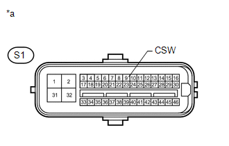
INSPECT SKID CONTROL ECU (CSW TERMINAL) |
(a) Disconnect the S1 skid control ECU (master cylinder solenoid) connector.
|
(b) Measure the resistance according to the value(s) in the table below. Standard Resistance:
|
|
(c) Reconnect the S1 skid control ECU (master cylinder solenoid) connector.
| NG | |
GO TO STEP 4 |
|
|
3. |
READ VALUE USING TECHSTREAM (TRAC/VSC OFF MODE) |
(a) Turn the ignition switch off.
(b) Connect the Techstream to the DLC3.
(c) Turn the ignition switch to ON.
(d) Turn the Techstream on.
(e) Enter the following menus: Chassis / ABS/VSC/TRAC / Data List.
ABS/VSC/TRAC|
Tester Display |
Measurement Item |
Control Range |
Diagnostic Note |
|---|---|---|---|
|
TRAC/VSC Off Mode |
TRAC/VSC off mode/ Normal, TRC OFF, Unknown or VSC OFF |
Normal: Normal mode TRC OFF: TRAC OFF mode VSC OFF: VSC OFF mode |
- |
(f) Check that the mode display changes according to VSC OFF switch operation.
OK:
Display changes according to switch operation.
| OK | |
GO TO METER / GAUGE SYSTEM (HOW TO PROCEED WITH TROUBLESHOOTING) |
| NG | |
REPLACE MASTER CYLINDER SOLENOID |
|
4. |
INSPECT VSC OFF SWITCH |
| NG | |
REPLACE VSC OFF SWITCH |
|
|
5. |
INSPECT ROOF CONSOLE BOX ASSEMBLY (MASTER CYLINDER SOLENOID - VSC OFF SWITCH) |
| A | |
REPAIR OR REPLACE HARNESS OR CONNECTOR (MASTER CYLINDER SOLENOID - ROOF CONSOLE BOX ASSEMBLY) |
| B | |
REPLACE ROOF CONSOLE BOX ASSEMBLY |
| C | |
REPLACE ROOF CONSOLE BOX ASSEMBLY |
 Brake Warning Light Remains ON
DESCRIPTION
The BRAKE warning light comes on when brake fluid is insufficient, the parking
brake is applied or the EBD is defective.
WIRING DIAGRAM
CAUTION / NOTICE / HINT
NOTICE:
Whe ...
 TRAC OFF Indicator Light Remains ON
DESCRIPTION
In 2WD mode:
Operation of the VSC OFF switch changes the vehicle between normal mode,
TRAC OFF mode (AUTO LSD mode) and VSC OFF mode. During normal mode, pressing
the VS ...
Other materials:
FCM Destination Information Uninitialized (C1AAA)
DESCRIPTION
When the forward recognition camera is replaced with a new one, the new forward
recognition camera attempts to store the country specification information received
from the main body ECU (multiplex network body ECU). If the forward recognition
camera cannot store the country speci ...
Noise Filter(for 2tr-fe)
Components
COMPONENTS
ILLUSTRATION
Removal
REMOVAL
PROCEDURE
1. DISCONNECT CABLE FROM NEGATIVE BATTERY TERMINAL
2. REMOVE AIR CLEANER ASSEMBLY
(See page )
3. REMOVE RADIO SETTING CONDENSER
(a) Disconnect the connector.
(b) Remove the tape and the radio setting condenser.
Instal ...
Check Bus 2 Lines for Short Circuit
DESCRIPTION
There may be a short circuit between the CAN main bus lines and/or CAN branch
lines when the resistance between terminals 18 (CA4H) and 17 (CA4L) of the central
gateway ECU (network gateway ECU) is below 54 Ω.
Detection Item
Trouble Area
Resi ...
