Toyota Tacoma (2015-2018) Service Manual: Electrical Key Oscillator(for Rear Floor)
Components
COMPONENTS
ILLUSTRATION
Installation
INSTALLATION
PROCEDURE
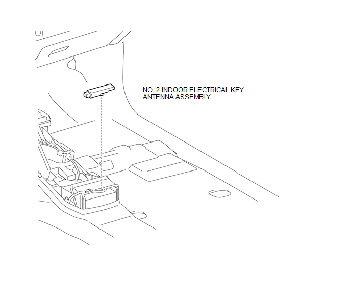
1. INSTALL NO. 2 INDOOR ELECTRICAL KEY ANTENNA ASSEMBLY
(a) Engage the clamp to install the No. 2 indoor electrical key antenna assembly.
(b) Connect the connector.
2. INSTALL REAR CONSOLE BOX ASSEMBLY
(See page .gif) )
)
Removal
REMOVAL
PROCEDURE
1. REMOVE REAR CONSOLE BOX ASSEMBLY
(See page .gif) )
)
2. REMOVE NO. 2 INDOOR ELECTRICAL KEY ANTENNA ASSEMBLY
|
(a) Disconnect the connector. |
|
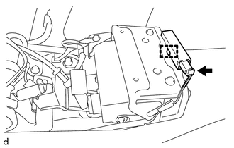
(b) Using a clip remover, disengage the clamp to remove the No. 2 indoor electrical key antenna assembly.
 Electrical Key Oscillator(for Front Floor)
Components
COMPONENTS
ILLUSTRATION
Installation
INSTALLATION
PROCEDURE
1. INSTALL NO. 1 INDOOR ELECTRICAL KEY ANTENNA ASSEMBLY
(a) Engage the clamp to install the No. 1 indoor electrical ...

Other materials:
On-vehicle Inspection
ON-VEHICLE INSPECTION
PROCEDURE
1. INSPECT BRAKE MASTER CYLINDER FLUID PRESSURE CHANGE
(a) Inspect the battery positive voltage.
Battery positive voltage:
10 to 14 V
(b) Turn the ignition switch to OFF, and depress the brake pedal more than 20
times.
HINT:
When pressure in the accumulator ...
Dtc Check / Clear
DTC CHECK / CLEAR
NOTICE:
When the diagnosis system is changed from normal mode to check mode or vice versa,
all DTCs and freeze frame data recorded in normal mode are cleared. Before changing
modes, always check and make a note of DTCs and freeze frame data.
HINT:
DTCs which are sto ...
Air Outlet Damper Position Sensor Circuit (B1433/33)
DESCRIPTION
This sensor detects the position of the mode damper and sends the appropriate
signals to the air conditioning amplifier assembly. The position sensor is built
into the No. 1 air conditioning radiator damper servo sub-assembly (for mode switching).
DTC No.
DTC ...
