Toyota Tacoma (2015-2018) Service Manual: Removal
REMOVAL
CAUTION / NOTICE / HINT
HINT:
- Use the same procedures for both the LH and RH sides.
- The procedure described below is for the LH side.
PROCEDURE
1. REMOVE FRONT DOOR LOWER FRAME BRACKET GARNISH
.gif)
2. REMOVE FRONT DOOR INSIDE HANDLE BEZEL PLUG
3. REMOVE FRONT ARMREST BASE UPPER PANEL SUB-ASSEMBLY
4. REMOVE FRONT DOOR TRIM BOARD SUB-ASSEMBLY
5. REMOVE OUTER REAR VIEW MIRROR ASSEMBLY
|
(a) Disconnect the connector. |
|
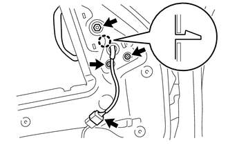
(b) Remove the 3 nuts.
(c) Disengage the claw to remove the outer rear view mirror assembly.
 Components
COMPONENTS
ILLUSTRATION
ILLUSTRATION
...
 Disassembly
DISASSEMBLY
CAUTION / NOTICE / HINT
HINT:
Use the same procedures for both the LH and RH sides.
The procedure described below is for the LH side.
PROCEDURE
1. REMOVE OUTER MIRRO ...
Other materials:
Components
COMPONENTS
ILLUSTRATION
*A
w/ Fuel Tank Cover
*B
for Hydraulic Brake Booster
*1
FUEL TANK ASSEMBLY
*2
FUEL TANK INLET PIPE SUB-ASSEMBLY
*3
FUEL TANK VENT HOSE SUB-ASSEMBLY
...
Operation Check
OPERATION CHECK
CHECK LANE DEPARTURE ALERT MAIN SWITCH
(a) Check the lane departure alert main switch (steering pad switch assembly)
on/off operation.
(1) Turn the ignition switch to ON.
(2) Confirm that the lane departure alert indicator (green) in the combination
meter assembly illuminates ...
Mechanical System Tests
MECHANICAL SYSTEM TESTS
1. STALL SPEED TEST
HINT:
This test is to check the overall performance of the engine and transmission.
CAUTION:
This test should be done on a paved surface (a surface that is not slippery).
To ensure safety, perform this test in an open and level area tha ...
