Toyota Tacoma (2015-2018) Service Manual: Power Outlet Socket(for Front Side)
Components
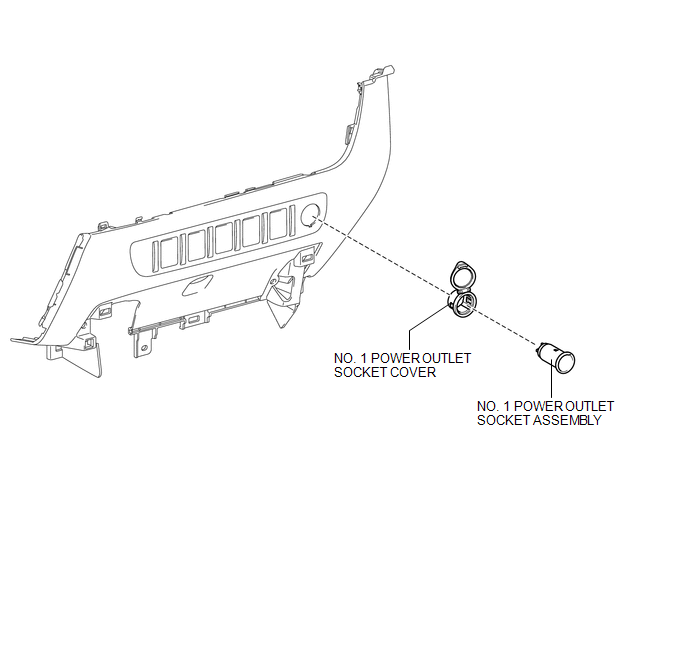
COMPONENTS
ILLUSTRATION
Removal
REMOVAL
PROCEDURE
1. REMOVE INSTRUMENT PANEL LOWER CENTER FINISH PANEL
(See page .gif) )
)
2. REMOVE NO. 1 POWER OUTLET SOCKET ASSEMBLY
|
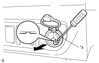
(a) Using a screwdriver with its tip wrapped in protective tape, disengage the 2 claws to remove the No. 1 power outlet socket assembly as shown in the illustration. Text in Illustration
|
|
3. REMOVE NO. 1 POWER OUTLET SOCKET COVER
|
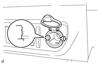
(a) Disengage the 2 claws to remove the No. 1 power outlet socket cover. |
|
Installation
INSTALLATION
PROCEDURE
1. INSTALL NO. 1 POWER OUTLET SOCKET COVER
(a) Engage the 2 claws to install the No. 1 power outlet socket cover.
2. INSTALL NO. 1 POWER OUTLET SOCKET ASSEMBLY
|
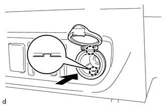
(a) Engage the 2 claws to install the No. 1 power outlet socket assembly as shown in the illustration. |
|
3. INSTALL INSTRUMENT PANEL LOWER CENTER FINISH PANEL
(See page .gif) )
)
 Inverter Relay
On-vehicle Inspection
ON-VEHICLE INSPECTION
PROCEDURE
1. INSPECT INVERTER RELAY
(a) Check the resistance.
(1) Measure the resistance according to the value(s) in the table below.
...
 Power Outlet Socket(for Rear Side)
Components
COMPONENTS
ILLUSTRATION
*1
USB CHARGER SOCKET
-
-
Removal
REMOVAL
PROCEDURE
1. REMOVE REAR CONSOLE BOX ASSEMBLY
Click here ...
Other materials:
Utility
UTILITY
NOTICE:
When replacing the millimeter wave radar sensor assembly, always replace
it with a new one. If a millimeter wave radar sensor assembly which was
installed to another vehicle is used, the information stored in it will
not match the information from the vehicle. A ...
Power Outlet Socket(for Rear Side)
Components
COMPONENTS
ILLUSTRATION
*1
USB CHARGER SOCKET
-
-
Removal
REMOVAL
PROCEDURE
1. REMOVE REAR CONSOLE BOX ASSEMBLY
Click here
2. REMOVE USB CHARGER SOCKET
(a) Disengage the 4 claws to remove the USB charger soc ...
Installation
INSTALLATION
CAUTION / NOTICE / HINT
HINT:
Use the same procedure for the RH and LH sides.
The procedure listed below is for the LH side.
PROCEDURE
1. INSTALL FRONT NO. 1 SPEAKER ASSEMBLY
(a) Install the front No. 1 speaker assembly with the 4 screws.
NOTICE:
Do not touch t ...
