Toyota Tacoma (2015-2018) Service Manual: 4WD Control ECU Communication Stop Mode
DESCRIPTION
|
Detection Item |
Symptom |
Trouble Area |
|---|---|---|
|
4WD Control ECU Communication Stop Mode |
Either condition is met:
|
|
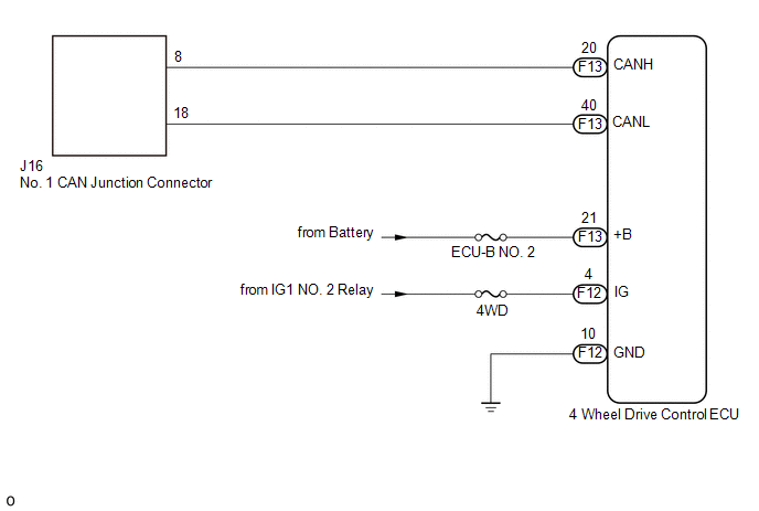
WIRING DIAGRAM
CAUTION / NOTICE / HINT
CAUTION:
When performing the confirmation driving pattern, obey all speed limits and traffic laws.
NOTICE:
- Because the order of diagnosis is important to allow correct diagnosis,
make sure to begin troubleshooting using How to Proceed with Troubleshooting
when CAN communication system related DTCs are output.
Click here
.gif)
- Before measuring the resistance of the CAN bus, turn the ignition switch off and leave the vehicle for 1 minute or more without operating the key or any switches, or opening or closing the doors. After that, disconnect the cable from the negative (-) battery terminal and leave the vehicle for 1 minute or more before measuring the resistance.
- After turning the ignition switch off, waiting time may be required
before disconnecting the cable from the negative (-) battery terminal. Therefore,
make sure to read the disconnecting the cable from the negative (-) battery
terminal notices before proceeding with work.
Click here
- Some parts must be initialized and set when replacing or removing and
installing parts.
Click here
- After performing repairs, perform the DTC check procedure and confirm
that the DTCs are not output again.
DTC check procedure: Turn the ignition switch to ON and wait for 1 minute or more. Then operate the suspected malfunctioning system and drive the vehicle at 60 km/h (37 mph) or more for 5 minutes or more.
- After the repair, perform the CAN bus check and check that all the ECUs
and sensors connected to the CAN communication system are displayed as normal.
Click here
- Inspect the fuses for circuits related to this system before performing the following procedure.
HINT:
- Before disconnecting related connectors for inspection, push in on each connector body to check that the connector is not loose or disconnected.
- When a connector is disconnected, check that the terminals and connector body are not cracked, deformed or corroded.
PROCEDURE
|
1. |
CHECK FOR OPEN IN CAN BUS LINES (4 WHEEL DRIVE CONTROL ECU BRANCH LINE) |
(a) Disconnect the cable from the negative (-) battery terminal.
|
(b) Disconnect the 4 wheel drive control ECU connector. |
|
(c) Measure the resistance according to the value(s) in the table below.
Standard Resistance:
|
Tester Connection |
Condition |
Specified Condition |
|---|---|---|
|
F13-20 (CANH) - F13-40 (CANL) |
Cable disconnected from negative (-) battery terminal |
54 to 69 Ω |
|
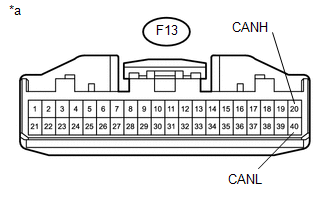
*a |
Front view of wire harness connector (to 4 Wheel Drive Control ECU) |
| NG | .gif) |
REPAIR OR REPLACE CAN BRANCH LINE OR CONNECTOR (4 WHEEL DRIVE CONTROL ECU) |
|
.gif)
|
2. |
CHECK HARNESS AND CONNECTOR (POWER SOURCE CIRCUIT) |
(a) Disconnect the 4 wheel drive control ECU connector.
|
(b) Measure the resistance according to the value(s) in the table below. Standard Resistance:
|
|
(c) Connect the cable to the negative (-) battery terminal.
(d) Measure the voltage according to the value(s) in the table below.
Standard Voltage:
|
Tester Connection |
Switch Condition |
Specified Condition |
|---|---|---|
|
F13-21 (+B) - Body ground |
Always |
11 to 14 V |
|
F12-4 (IG) - Body ground |
Ignition switch ON |
11 to 14 V |
|
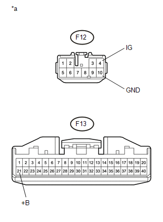
*a |
Front view of wire harness connector (to 4 Wheel Drive Control ECU) |
| OK | |
REPLACE 4 WHEEL DRIVE CONTROL ECU |
| NG | |
REPAIR OR REPLACE HARNESS OR CONNECTOR (POWER SOURCE CIRCUIT) |
 Combination Meter ECU Communication Stop Mode
DESCRIPTION
Detection Item
Symptom
Trouble Area
Combination Meter ECU Communication Stop Mode
Either condition is met:
Commu ...
 Blind Spot Monitor Sensor Communication Stop Mode
DESCRIPTION
Detection Item
Symptom
Trouble Area
Blind Spot Monitor Sensor Communication Stop Mode
Either Condition is met:
C ...
Other materials:
Precaution
PRECAUTION
1. IGNITION SWITCH EXPRESSIONS
(a) The type of ignition switch used on this model differs according to the specifications
of the vehicle. The expressions listed in the table below are used in this section.
Expression
Ignition Switch (Position)
Engine ...
FCM Destination Information Uninitialized (C1AAA)
DESCRIPTION
When the forward recognition camera is replaced with a new one, the new forward
recognition camera attempts to store the country specification information received
from the main body ECU (multiplex network body ECU). If the forward recognition
camera cannot store the country speci ...
Reporting safety defects for U.S. owners
If you believe that your vehicle has a defect which could cause a crash or could
cause injury or death, you should immediately inform the National Highway Traffic
Safety Administration (NHTSA) in addition to notifying Toyota Motor Sales, U.S.A.,
Inc. (Toll-free: 1-800-331-4331).
If NHTSA rece ...
