Toyota Tacoma (2015-2018) Service Manual: Driver Side Door ECU Communication Stop (B2321)
DESCRIPTION
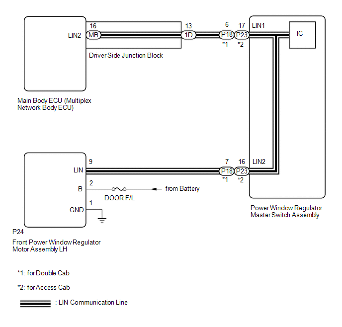
This DTC is stored when LIN communication between the front power window regulator motor assembly LH and main body ECU (multiplex network body ECU) stops for 10 seconds or more.
|
DTC No. |
DTC Detection Condition |
Trouble Area |
|---|---|---|
|
B2321 |
No communication between front power window regulator motor assembly LH and main body ECU (multiplex network body ECU) for 10 seconds or more. |
|
WIRING DIAGRAM
CAUTION / NOTICE / HINT
NOTICE:
- Inspect the fuses for circuits related to this system before performing the following inspection procedure.
- If the main body ECU (multiplex network body ECU) is replaced, refer
to Registration (See page
.gif) )
) - When a power window regulator motor assembly is replaced or removed
and reinstalled, it requires initialization (See page
).
PROCEDURE
|
1. |
CHECK DTC OUTPUT |
(a) Clear the DTCs (See page ).
(b) Recheck for DTCs.
|
Result |
Proceed to |
|---|---|
|
Only DTC B2321 is output. |
A |
|
DTC B1206 and B2321 are output simultaneously. |
B |
HINT:
When DTC B1206 and B2321 are output simultaneously, perform troubleshooting for DTC B1206 first.
| B | .gif) |
GO TO DTC B1206 |
|
.gif)
|
2. |
CHECK HARNESS AND CONNECTOR (POWER WINDOW REGULATOR MASTER SWITCH ASSEMBLY - FRONT POWER WINDOW REGULATOR MOTOR ASSEMBLY LH) |
(a) for Double Cab
(1) Disconnect the P18 power window regulator master switch assembly connector.
(2) Disconnect the P24 front power window regulator motor assembly LH connector.
(3) Measure the resistance according to the value(s) in the table below.
Standard Resistance:
|
Tester Connection |
Condition |
Specified Condition |
|---|---|---|
|
P18-7 (LIN2) - P24-9 (LIN) |
Always |
Below 1 Ω |
|
P18-7 (LIN2) or P24-9 (LIN) - Body ground |
Always |
10 kΩ or higher |
(b) for Access Cab
(1) Disconnect the P23 power window regulator master switch assembly connector.
(2) Disconnect the P24 front power window regulator motor assembly LH connector.
(3) Measure the resistance according to the value(s) in the table below.
Standard Resistance:
|
Tester Connection |
Condition |
Specified Condition |
|---|---|---|
|
P23-16 (LIN2) - P24-9 (LIN) |
Always |
Below 1 Ω |
|
P23-16 (LIN2) or P24-9 (LIN) - Body ground |
Always |
10 kΩ or higher |
| NG | |
REPAIR OR REPLACE HARNESS OR CONNECTOR |
|
|
3. |
INSPECT POWER WINDOW REGULATOR MASTER SWITCH ASSEMBLY |
(a) for Double Cab
|
(1) Remove the power window regulator master switch assembly. |
|
(2) Measure the resistance according to the value(s) in the table below.
Standard Resistance:
|
Tester Connection |
Condition |
Specified Condition |
|---|---|---|
|
6 (LIN1) - 7 (LIN2) |
Always |
Below 1 Ω |
|
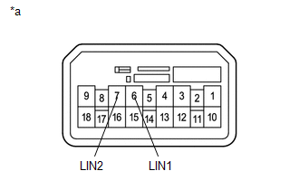
*a |
Component without harness connected (Power Window Regulator Master Switch Assembly) |
(b) for Access Cab
|
(1) Remove the power window regulator master switch assembly. |
|
(2) Measure the resistance according to the value(s) in the table below.
Standard Resistance:
|
Tester Connection |
Condition |
Specified Condition |
|---|---|---|
|
17 (LIN1) - 16 (LIN2) |
Always |
Below 1 Ω |
|
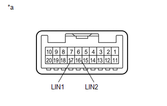
*a |
Component without harness connected (Power Window Regulator Master Switch Assembly) |
| NG | |
REPLACE POWER WINDOW REGULATOR MASTER SWITCH ASSEMBLY |
|
|
4. |
CHECK HARNESS AND CONNECTOR (FRONT POWER WINDOW REGULATOR MOTOR ASSEMBLY LH - POWER SOURCE CIRCUIT) |
(a) Disconnect the P24 front power window regulator motor assembly LH connector.
(b) Measure the voltage according to the value(s) in the table below.
Standard Voltage:
|
Tester Connection |
Condition |
Specified Condition |
|---|---|---|
|
P24-2 (B) - Body ground |
Always |
11 to 14 V |
(c) Measure the resistance according to the value(s) in the table below.
Standard Resistance:
|
Tester Connection |
Condition |
Specified Condition |
|---|---|---|
|
P24-1 (GND) - Body ground |
Always |
Below 1 Ω |
| NG | |
REPAIR OR REPLACE HARNESS OR CONNECTOR |
|
|
5. |
REPLACE FRONT POWER WINDOW REGULATOR MOTOR ASSEMBLY LH |
(a) Replace the front power window regulator motor assembly LH.
|
|
6. |
CHECK DTC OUTPUT |
(a) Clear the DTCs (See page ).
(b) Check for DTCs.
OK:
DTC B2321 is not output.
| OK | |
END (FRONT POWER WINDOW REGULATOR MOTOR ASSEMBLY LH) WAS DEFECTIVE) |
| NG | |
REPLACE MAIN BODY ECU (MULTIPLEX NETWORK BODY ECU) |
 Sliding Roof ECU Communication Stop (B1273)
DESCRIPTION
This DTC is stored when LIN communication between the sliding roof ECU (sliding
roof drive gear sub-assembly) and main body ECU (multiplex network body ECU) stops
for 10 seconds or mo ...
 LIN Communication Bus Malfunction (B2325)
DESCRIPTION
The main body ECU (multiplex network body ECU) monitors communication between
all the ECUs connected to the door bus lines. When the main body ECU (multiplex
network body ECU) detects ...
Other materials:
Terminals Of Ecu
TERMINALS OF ECU
CHECK ECM
HINT:
The standard voltage, resistance and waveform between each pair of the ECM terminals
is shown in the table below. The appropriate conditions for checking each pair of
the terminals is also indicated. The result of checks should be compared with the
standar ...
On-vehicle Inspection
ON-VEHICLE INSPECTION
PROCEDURE
1. INSPECT LOWER NO. 2 INSTRUMENT PANEL AIRBAG ASSEMBLY (for Vehicle not Involved
in Collision)
(a) Perform a diagnostic system check (See page
).
(b) With the lower No. 2 instrument panel airbag assembly ...
Front Camera Module Incorrect Axial Gap (C1AA8)
DESCRIPTION
If the millimeter wave radar sensor assembly detects that the beam axis of the
forward recognition camera is misaligned, it will store DTC C1AA8.
DTC No.
Detection Item
DTC Detection Condition
Trouble Area
C1AA8
...
