Toyota Tacoma (2015-2018) Service Manual: Back-up Light Switch
Components
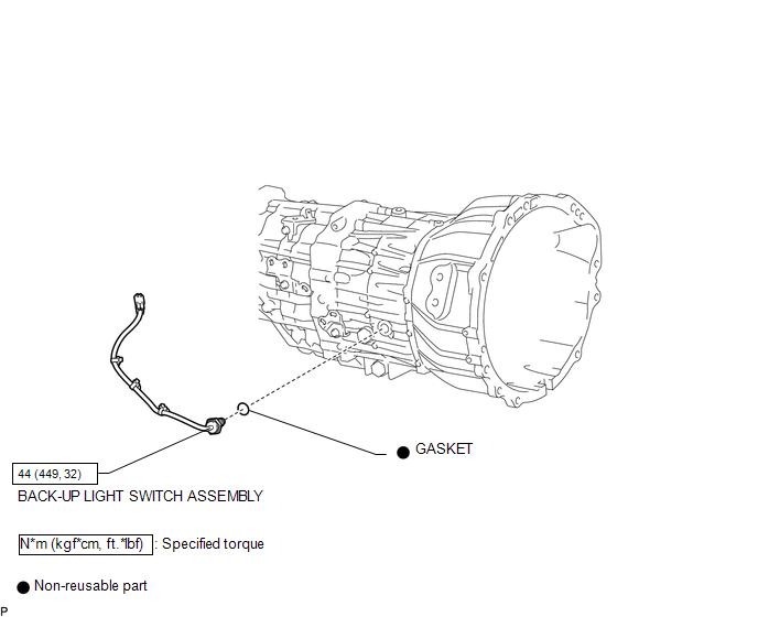
COMPONENTS
ILLUSTRATION
Inspection
INSPECTION
PROCEDURE
1. INSPECT BACK-UP LIGHT SWITCH ASSEMBLY
|
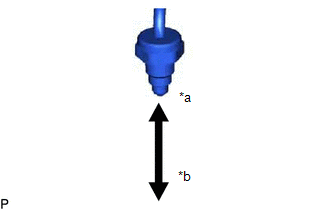
(a) Measure the resistance according to the value(s) in the table below. Text in Illustration
Standard Resistance:
If the result is not as specified, replace the back-up light switch assembly. |
|
Removal
REMOVAL
PROCEDURE
1. REMOVE SHIFT LEVER BOOT ASSEMBLY
.gif)
2. REMOVE BACK-UP LIGHT SWITCH ASSEMBLY
|
(a) Disconnect the connector. |
|
|
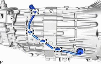
(b) Detach the 4 clamps. |
|
|
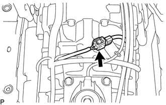
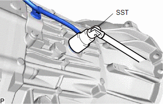
(c) Using SST, remove the back-up light switch assembly and gasket from the transmission case. SST: 09817-16011 |
|
Installation
INSTALLATION
PROCEDURE
1. INSTALL BACK-UP LIGHT SWITCH ASSEMBLY
|
(a) Using SST, install a new gasket and the back-up light switch assembly to the transmission case. SST: 09817-16011 Torque: 44 N·m {449 kgf·cm, 32 ft·lbf} |
|
.png)
(b) Attach the 4 clamps.
(c) Connect the connector.
2. INSTALL SHIFT LEVER BOOT ASSEMBLY
.gif)

 Counter Gear
...
Other materials:
Clutch Release Cylinder(for Rc62f)
Components
COMPONENTS
ILLUSTRATION
Disassembly
DISASSEMBLY
PROCEDURE
1. REMOVE CLUTCH RELEASE CYLINDER KIT
(a) Remove the boot from the cylinder body.
(b) Remove the push rod from the boot.
(c) Using compressed air, remove the piston together with the spring
from the cy ...
Problem Symptoms Table
PROBLEM SYMPTOMS TABLE
HINT:
Use the table below to help determine the cause of problem symptoms.
If multiple suspected areas are listed, the potential causes of the symptoms
are listed in order of probability in the "Suspected Area" column of the
table. Check each sy ...
Power Outlet Socket(for Front Side)
Components
COMPONENTS
ILLUSTRATION
Removal
REMOVAL
PROCEDURE
1. REMOVE INSTRUMENT PANEL LOWER CENTER FINISH PANEL
(See page )
2. REMOVE NO. 1 POWER OUTLET SOCKET ASSEMBLY
(a) Using a screwdriver with its tip wrapped in protective tape, disengage
the 2 claws to remove t ...
