Toyota Tacoma (2015-2018) Service Manual: All Doors LOCK/UNLOCK Functions do not Operate Via Door Control Switch
DESCRIPTION
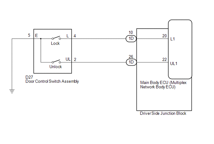
The main body ECU (multiplex network body ECU) receives switch signals from the door control switch assembly on the front passenger door and activates the door lock motor on each door according to these signals.
WIRING DIAGRAM
PROCEDURE
|
1. |
READ VALUE USING TECHSTREAM (Door Lock SW-Lock, Door Lock SW-Unlock) |
(a) Connect the Techstream to the DLC3.
(b) Turn the ignition switch to ON.
(c) Turn the Techstream on.
(d) Enter the following menus: Body Electrical / Main Body / Data List.
(e) Read the Data List according to the display on the Techstream.
Main Body|
Tester Display |
Measurement Item/Range |
Normal Condition |
Diagnostic Note |
|---|---|---|---|
|
Door Lock SW-Lock |
Door control switch (power window regulator master switch assembly) or door control switch assembly lock signal/ON or OFF |
ON: Lock side of door control switch (power window regulator master switch assembly) or door control switch assembly pushed OFF: Lock side of door control switch (power window regulator master switch assembly) and door control switch assembly not pushed |
- |
|
Door Lock SW-Unlock |
Door control switch (power window regulator master switch assembly) or door control switch assembly unlock signal/ON or OFF |
ON: Unlock side of door control switch (power window regulator master switch assembly) or door control switch assembly pushed OFF: Unlock side of door control switch (power window regulator master switch assembly) or door control switch assembly not pushed |
- |
OK:
The Techstream indicates ON or OFF according to the switch operation shown in the table.
| OK | .gif) |
REPLACE MAIN BODY ECU (MULTIPLEX NETWORK BODY ECU) |
|
.gif)
|
2. |
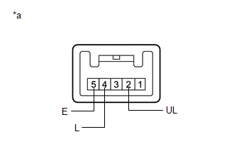
INSPECT DOOR CONTROL SWITCH ASSEMBLY |
(a) Remove the door control switch assembly (See page
.gif) ).
).
(b) Inspect the door control switch assembly.
|
(1) Measure the resistance according to the value(s) in the table below. Standard Resistance:
|
|
| NG | |
REPLACE DOOR CONTROL SWITCH ASSEMBLY |
|
|
3. |
CHECK HARNESS AND CONNECTOR (DOOR CONTROL SWITCH ASSEMBLY - MAIN BODY ECU (MULTIPLEX NETWORK BODY ECU)) |
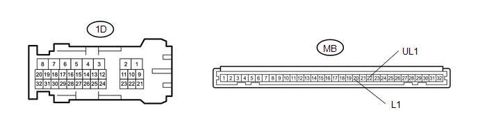
(a) Disconnect the 1D driver side junction block connector.
(b) Measure the resistance according to the value(s) in the table below.
Standard Resistance:
|
Tester Connection |
Condition |
Specified Condition |
|---|---|---|
|
D27-2 (UL) - 1D-26 (UL1) |
Always |
Below 1 Ω |
|
D27-4 (L) - 1D-10 (L1) |
Always |
Below 1 Ω |
|
D27-5 (E) - Body ground |
Always |
Below 1 Ω |
|
D27-2 (UL) - Body ground |
Always |
10 kΩ or higher |
|
D27-4 (L) - Body ground |
Always |
10 kΩ or higher |
| NG | |
REPAIR OR REPLACE HARNESS OR CONNECTOR |
|
|
4. |
CHECK DRIVER SIDE JUNCTION BLOCK |
(a) Remove the driver side junction block (See page
).
Standard Resistance:
|
Tester Connection |
Condition |
Specified Condition |
|---|---|---|
|
1D-16 - MB-22 (UL1) |
Always |
Below 1 Ω |
|
1D-23 - MB-20 (L1) |
Always |
Below 1 Ω |
|
1D-16 - Body ground |
Always |
10 kΩ or higher |
|
1D-23 (L1) - Body ground |
Always |
10 kΩ or higher |
|
*a |
Component without harness connected (driver side junction block) |
- |
- |
| OK | |
REPLACE MAIN BODY ECU (MULTIPLEX NETWORK BODY ECU) |
| NG | |
REPLACE DRIVER SIDE JUNCTION BLOCK |
 All Doors LOCK/UNLOCK Functions do not Operate Via Door Control Switch or Door
Key Cylinder
All Doors LOCK/UNLOCK Functions do not Operate Via Door Control Switch or Door
Key Cylinder
DESCRIPTION
The main body ECU (multiplex network body ECU) receives switch signals from the
power window regulator master switch assembly and driver door key cylinder lock
or unlock switch signal ...

Other materials:
Accumulator Low Pressure (C1452)
DESCRIPTION
DTC Code
DTC Detection Condition
Trouble Area
C1452
After braking, the fluid pressure inside the accumulator is below the
threshold within 3.2 seconds.
Hydraulic circuit
Accumulator pressure sen ...
Auto Down Operation does not Fully Open Power Window (Catch Protection Function
is Activated)
DESCRIPTION
If a front door glass or the power window regulator motor assembly (for driver
door) or power window regulator motor assembly (front passenger door) does not operate
smoothly, the catch protection function may be triggered automatically, resulting
in the auto down operation being ...
Invalid Data Received from Deceleration Sensor (C1442,C1443)
DESCRIPTION
The airbag sensor assembly has a built-in yaw rate and acceleration sensor.
The skid control ECU (brake actuator assembly) receives signals from the yaw
rate and acceleration sensor (airbag sensor assembly) via the CAN communication
system.
DTC No.
Detection ...
