Toyota Tacoma (2015-2018) Service Manual: All Doors LOCK/UNLOCK Functions do not Operate Via Door Control Switch or Door Key Cylinder
DESCRIPTION
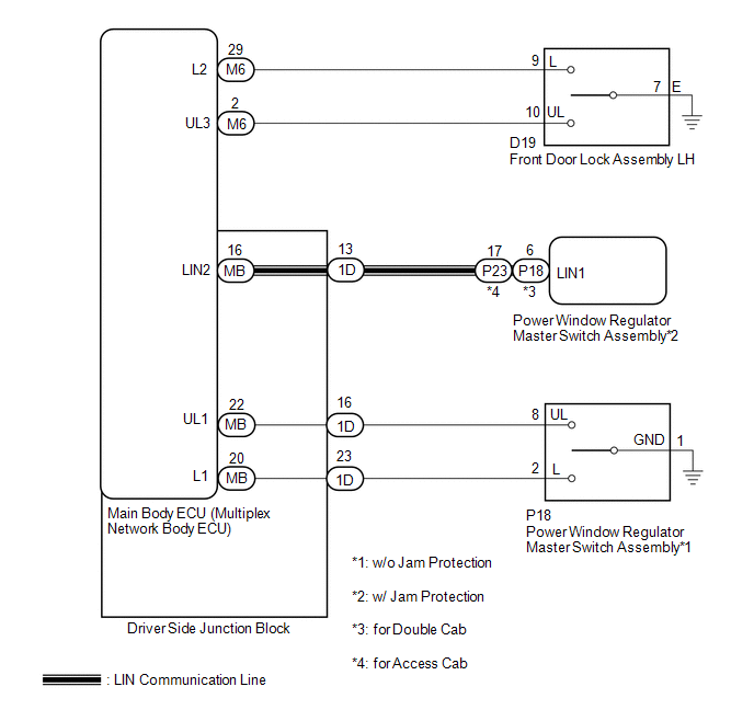
The main body ECU (multiplex network body ECU) receives switch signals from the power window regulator master switch assembly and driver door key cylinder lock or unlock switch signals from the front door lock assembly. The main body ECU (multiplex network body ECU) activates the door lock motor on each door according to these signals.
WIRING DIAGRAM
CAUTION / NOTICE / HINT
NOTICE:
The power door lock control system uses the LIN communication system. Inspect the communication function by following How to Proceed with Troubleshooting. Troubleshoot the power door lock control system after confirming that the communication systems are functioning properly.*1
- *1: w/ Jam Protection
PROCEDURE
|
1. |
CHECK DOOR LOCK OPERATION |
(a) Check door lock operation (See page .gif) ).
).
|
Result |
Proceed to |
|---|---|
|
All doors cannot be locked by power window regulator master switch assembly. (w/ Jam Protection) |
A |
|
All doors cannot be locked by power window regulator master switch assembly. (w/o Jam Protection) |
B |
|
All doors cannot be locked by driver door key cylinder |
C |
| B | .gif) |
GO TO STEP 8 |
| C | |
GO TO STEP 5 |
|
.gif)
|
2. |
CHECK FOR DTC (LIN COMMUNICATION SYSTEM) |
(a) Clear the DTCs (See page ).
(b) Recheck for DTCs.
OK:
DTC B1206 is not output.
| NG | |
GO TO LIN COMMUNICATION SYSTEM (DTC B1206) |
|
|
3. |
REPLACE POWER WINDOW REGULATOR MASTER SWITCH ASSEMBLY |
(a) Replace the power window regulator master switch assembly (See page
).
|
|
4. |
CHECK DOOR LOCK OPERATION |
(a) Check that all doors can be locked and unlocked by the power window regulator
master switch assembly (See page ).
OK:
All doors can be locked and unlocked by the power window regulator master switch assembly.
| OK | |
END (POWER WINDOW REGULATOR MASTER SWITCH ASSEMBLY WAS DEFECTIVE) |
| NG | |
REPLACE MAIN BODY ECU (MULTIPLEX NETWORK BODY ECU) |
|
5. |
READ VALUE USING TECHSTREAM (Door Key SW-Lock, D Door Key SW-UL) |
(a) Connect the Techstream to the DLC3.
(b) Turn the ignition switch to ON.
(c) Turn the Techstream on.
(d) Enter the following menus: Body Electrical / Main Body / Data List.
(e) Read the Data List according to the display on the Techstream.
Main Body|
Tester Display |
Measurement Item/Range |
Normal Condition |
Diagnostic Note |
|---|---|---|---|
|
Door Key SW-Lock |
Driver door key-linked lock/unlock switch lock signal/ON or OFF |
ON: Driver door key cylinder turned to lock position OFF: Driver door key cylinder not turned to lock position |
- |
|
D Door Key SW-UL |
Driver door key-linked lock/unlock switch unlock signal/ON or OFF |
ON: Driver door key cylinder turned to unlock position OFF: Driver door key cylinder not turned to unlock position |
- |
OK:
The Techstream indicates ON or OFF according to the key cylinder operation shown in the table.
| OK | |
REPLACE MAIN BODY ECU (MULTIPLEX NETWORK BODY ECU) |
|
|
6. |
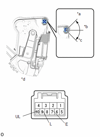
INSPECT FRONT DOOR LOCK ASSEMBLY LH |
(a) Remove the front door lock assembly LH (See page
).
(b) Inspect the front door lock assembly LH.
|
(1) Measure the resistance according to the value(s) in the table below. Standard Resistance:
|
|
| NG | |
REPLACE FRONT DOOR LOCK ASSEMBLY LH |
|
|
7. |
CHECK HARNESS AND CONNECTOR (FRONT DOOR LOCK ASSEMBLY LH - MAIN BODY ECU (MULTIPLEX NETWORK BODY ECU)) |
(a) Disconnect the M6 main body ECU (multiplex network body ECU) connector.
(b) Measure the resistance according to the value(s) in the table below.
Standard Resistance:
|
Tester Connection |
Condition |
Specified Condition |
|---|---|---|
|
D19-9 (L) - M6-29 (L2) |
Always |
Below 1 Ω |
|
D19-10 (UL) - M6-2 (UL3) |
Always |
Below 1 Ω |
|
D19-7 (E) - Body ground |
Always |
Below 1 Ω |
|
M6-29 (L2) - Body ground |
Always |
10 kΩ or higher |
|
M6-2 (UL3) - Body ground |
Always |
10 kΩ or higher |
| OK | |
REPLACE MAIN BODY ECU (MULTIPLEX NETWORK BODY ECU) |
| NG | |
REPAIR OR REPLACE HARNESS OR CONNECTOR |
|
8. |
READ VALUE USING TECHSTREAM (POWER WINDOW REGULATOR MASTER SWITCH ASSEMBLY) |
(a) Connect the Techstream to the DLC3.
(b) Turn the ignition switch to ON.
(c) Turn the Techstream on.
(d) Enter the following menus: Body Electrical / Main Body / Data List.
(e) Read the Data List according to the display on the Techstream.
Main Body|
Tester Display |
Measurement Item/Range |
Normal Condition |
Diagnostic Note |
|---|---|---|---|
|
Door Lock SW-Lock |
Door control switch (power window regulator master switch assembly) or door control switch assembly lock signal/ON or OFF |
ON: Lock side of door control switch (power window regulator master switch assembly) or door control switch assembly pushed OFF: Lock side of door control switch (power window regulator master switch assembly) and door control switch assembly not pushed |
- |
|
Door Lock SW-Unlock |
Door control switch (power window regulator master switch assembly) or door control switch assembly unlock signal/ON or OFF |
ON: Unlock side of door control switch (power window regulator master switch assembly) or door control switch assembly pushed OFF: Unlock side of door control switch (power window regulator master switch assembly) or door control switch assembly not pushed |
- |
OK:
The Techstream indicates ON or OFF according to the switch operation shown in the table.
| OK | |
REPLACE MAIN BODY ECU (MULTIPLEX NETWORK BODY ECU) |
|
|
9. |
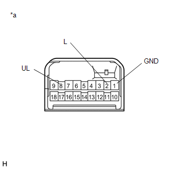
INSPECT POWER WINDOW REGULATOR MASTER SWITCH ASSEMBLY |
(a) Remove the power window regulator master switch assembly (See page
).
(b) Inspect the power window regulator master switch assembly.
|
(1) Measure the resistance according to the value(s) in the table below. Standard Resistance:
|
|
| NG | |
REPLACE POWER WINDOW REGULATOR MASTER SWITCH ASSEMBLY |
|
|
10. |
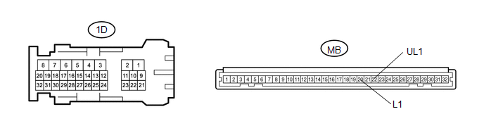
CHECK HARNESS AND CONNECTOR (POWER WINDOW MASTER SWITCH - MAIN BODY ECU (MULTIPLEX NETWORK BODY ECU)) |
(a) Disconnect the 1D driver side junction block connector.
(b) Measure the resistance according to the value(s) in the table below.
Standard Resistance:
|
Tester Connection |
Condition |
Specified Condition |
|---|---|---|
|
1D-16 (UL1) - P18-8 (UL) |
Always |
Below 1 Ω |
|
1D-23 (L1) - P18-2 (L) |
Always |
Below 1 Ω |
|
P18-1 (GND) - Body ground |
Always |
Below 1 Ω |
|
1D-16 (UL1) or P18-8 (UL) - Body ground |
Always |
10 kΩ or higher |
|
1D-23 (L1) or P18-2 (L) - Body ground |
Always |
10 kΩ or higher |
| NG | |
REPAIR OR REPLACE HARNESS OR CONNECTOR |
|
|
11. |
CHECK DRIVER SIDE JUNCTION BLOCK |
(a) Remove the driver side junction block (See page
).
Standard Resistance:
|
Tester Connection |
Condition |
Specified Condition |
|---|---|---|
|
1D-16 - MB-22 (UL1) |
Always |
Below 1 Ω |
|
1D-23 - MB-20 (L1) |
Always |
Below 1 Ω |
|
1D-16 - Body ground |
Always |
10 kΩ or higher |
|
1D-23 (L1) - Body ground |
Always |
10 kΩ or higher |
|
*a |
Component without harness connected (driver side junction block) |
- |
- |
| OK | |
REPLACE MAIN BODY ECU (MULTIPLEX NETWORK BODY ECU) |
| NG | |
REPLACE DRIVER SIDE JUNCTION BLOCK |
 Terminals Of Ecu
TERMINALS OF ECU
1. CHECK DRIVER SIDE JUNCTION BLOCK AND MAIN BODY ECU (MULTIPLEX NETWORK BODY
ECU)
(a) Disconnect the MB main body ECU (multiplex network body ECU) connectors.
(b) Measure the ...
 All Doors LOCK/UNLOCK Functions do not Operate Via Door Control Switch
DESCRIPTION
The main body ECU (multiplex network body ECU) receives switch signals from the
door control switch assembly on the front passenger door and activates the door
lock motor on each door ...
Other materials:
Engine Coolant Temperature Sensor
Components
COMPONENTS
ILLUSTRATION
Inspection
INSPECTION
PROCEDURE
1. INSPECT ENGINE COOLANT TEMPERATURE SENSOR
(a) Partially immerse the engine coolant temperature sensor in water and warm
up the water.
(b) Measure the resistance according to the value(s) in the table bel ...
Components
COMPONENTS
ILLUSTRATION
ILLUSTRATION
ILLUSTRATION
ILLUSTRATION
ILLUSTRATION
ILLUSTRATION
ILLUSTRATION
ILLUSTRATION
ILLUSTRATION
ILLUSTRATION
...
Diagnosis System
DIAGNOSIS SYSTEM
1. CHECK DLC3
(a) The vehicle ECUs use ISO 15765-4 communication protocol. The terminal arrangement
of the DLC3 complies with ISO 15031-3 and matches the ISO 15765-4 format.
Terminals No. (Symbols)
Terminal Description
Condition
Spe ...
