Toyota Tacoma (2015-2018) Service Manual: Air Outlet Control Servo Motor
Inspection
INSPECTION
PROCEDURE
1. INSPECT MODE CONTROL SERVO MOTOR
|
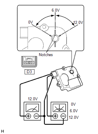
(a) Inspect the servo motor operation. (1) When 12V is applied between terminals 4 (IGN) and 1 (GND), and 0V is applied between terminals 2 (SIG) and 1 (GND), check that the line connecting the 2 notches moves to the 0V position. If the result is not as specified, replace the mode control servo motor. (2) When 12V is applied between terminals 4 (IGN) and 1 (GND), and 6V is applied between terminals 2 (SIG) and 1 (GND), check that the line connecting the 2 notches moves to the 6V position. If the result is not as specified, replace the mode control servo motor. (3) When 12V is applied between terminals 4 (IGN) and 1 (GND), and between terminals 2 (SIG) and 1 (GND), check that the line connecting the 2 notches moves to the 12V position. If the result is not as specified, replace the mode control servo motor. |
|
 Air Mix Control Servo Motor
Inspection
INSPECTION
PROCEDURE
1. INSPECT AIR MIX CONTROL SERVO MOTOR (for Manual Air Conditioning System)
(a) Inspect the servo motor operation.
Text in Illustration
...
 Ambient Temperature Sensor
Components
COMPONENTS
ILLUSTRATION
Inspection
INSPECTION
PROCEDURE
1. INSPECT AMBIENT TEMPERATURE SENSOR
(a) Measure the resistance according to the value(s) in the table below ...
Other materials:
Data List / Active Test
DATA LIST / ACTIVE TEST
1. DATA LIST
NOTICE:
In the table below, the values listed under "Normal Condition" are reference
values. Do not depend solely on these reference values when deciding whether a part
is faulty or not.
HINT:
Using the Techstream to read the Data List allows t ...
Tire Pressure Warning Light Circuit
DESCRIPTION
If the tire pressure warning ECU and receiver detects any problems, the tire
pressure warning light blinks for 1 minute then illuminates, and tire pressure monitoring
is disabled at the same time. At this time, the ECU stores a DTC in memory.
Connecting terminals TC and CG of the D ...
Extension Module Malfunction (B1552,B158A,B15BA)
DESCRIPTION
These DTCs are stored when a malfunction occurs in the stereo component tuner
assembly.
DTC No.
DTC Detection Condition
Trouble Area
B1552
Internal malfunction of the navigation ECU
Stereo component tuner assembl ...
