Toyota Tacoma (2015-2018) Service Manual: System Diagram
SYSTEM DIAGRAM
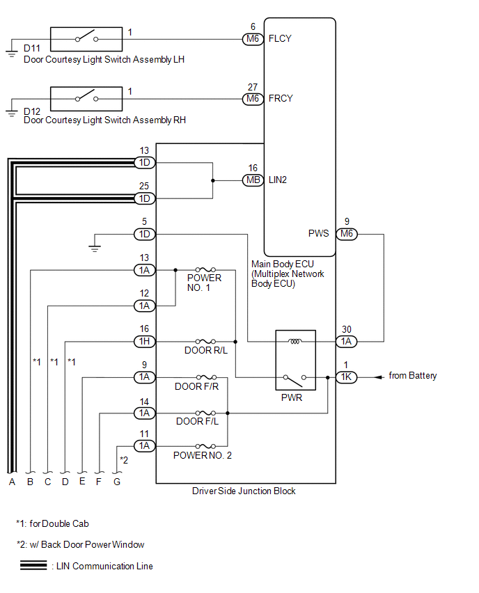
 Communication Table
|
Transmitting ECU |
Receiving ECU |
Signal |
Communication Method |
|---|---|---|---|
|
Power Window Regulator Master Switch Assembly |
Power Window Regulator Motor Assembly (for Driver Door) |
Power Window Regulator Motor Assembly (for Front Passenger Door) |
LIN |
|
Power Window Regulator Motor Assembly (for Front Passenger Door) |
Power window remote up and down signal |
LIN |
|
|
Main body ECU (multiplex network body ECU) |
|
Power window operation permission signal |
LIN |
 System Description
SYSTEM DESCRIPTION
1. POWER WINDOW CONTROL SYSTEM DESCRIPTION
(a) The power window control system controls the power window operation using
the power window regulator motors. The main controls of ...
 Customize Parameters
CUSTOMIZE PARAMETERS
PROCEDURE
1. CUSTOMIZE POWER WINDOW CONTROL SYSTEM
HINT:
The following items can be customized.
NOTICE:
When the customer requests a change in a function, first make ...
Other materials:
On-vehicle Inspection
ON-VEHICLE INSPECTION
PROCEDURE
1. INSPECT CAMSHAFT TIMING GEAR BOLT
(a) Remove the camshaft timing oil control solenoid assembly (See page
).
(b) Check that the plunger strokes when the plunger in the center of
the camshaft timing gear bolt is pressed.
Standard stroke:
4 ...
Removal
REMOVAL
PROCEDURE
1. PRECAUTION
NOTICE:
After turning the ignition switch off, waiting time may be required before disconnecting
the cable from the negative (-) battery terminal.
Therefore, make sure to read the disconnecting the cable from the negative (-)
battery terminal notices before p ...
Reassembly
REASSEMBLY
PROCEDURE
1. INSTALL CONSOLE COMPARTMENT DOOR HINGE SUB-ASSEMBLY
(a) Engage the 2 guides to install the console compartment door hinge
sub-assembly.
(b) Install the 4 screws.
(c) Engage the 2 guides and 4 claws ...
