Toyota Tacoma (2015-2018) Service Manual: Air Mix Control Servo Motor
Inspection
INSPECTION
PROCEDURE
1. INSPECT AIR MIX CONTROL SERVO MOTOR (for Manual Air Conditioning System)
|
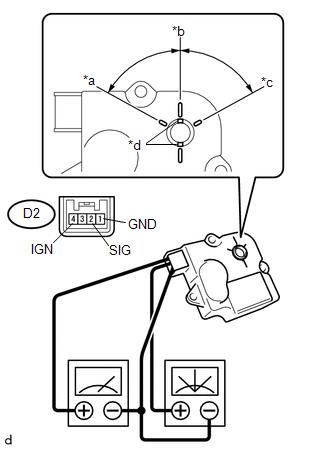
(a) Inspect the servo motor operation. Text in Illustration
(1) When 12 V is applied between terminals 4 (IGN) and 1 (GND), and 0 V is applied between terminals 2 (SIG) and 1 (GND), check that the line connecting the 2 notches moves to the 0 V position. If the result is not as specified, replace the air mix control servo motor. (2) When 12 V is applied between terminals 4 (IGN) and 1 (GND), and 6 V is applied between terminals 2 (SIG) and 1 (GND), check that the line connecting the 2 notches moves to the 6 V position. If the result is not as specified, replace the air mix control servo motor. (3) When 12 V is applied between terminals 4 (IGN) and 1 (GND), and between terminals 2 (SIG) and 1 (GND), check that the line connecting the 2 notches moves to the 12 V position. If the result is not as specified, replace the air mix control servo motor. |
|
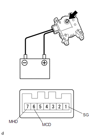
2. INSPECT AIR MIX CONTROL SERVO MOTOR (for Automatic Air Conditioning System)
|
(a) Inspect the servo motor operation. (1) Connect the positive (+) lead from the battery to terminal 7 (MHD) and negative (-) lead to terminals 1 (SG), then check that the shaft rotates clockwise smoothly. (2) Connect the positive (+) lead from the battery to terminal 6 (MCD) and negative (-) lead to terminal 1 (SG) then check that the shaft rotates counterclockwise smoothly. If the operations are not as specified, replace the air mix control servo motor. |
|
 Air Inlet Control Servo Motor
Inspection
INSPECTION
PROCEDURE
1. INSPECT AIR INLET CONTROL SERVO MOTOR
(a) Inspect the servo motor operation.
(1) Connect the positive (+) lead from the battery to terminal 1 (FR ...
 Air Outlet Control Servo Motor
Inspection
INSPECTION
PROCEDURE
1. INSPECT MODE CONTROL SERVO MOTOR
(a) Inspect the servo motor operation.
(1) When 12V is applied between terminals 4 (IGN) and 1 (GND), and 0V
...
Other materials:
Air Inlet Control Servo Motor
Inspection
INSPECTION
PROCEDURE
1. INSPECT AIR INLET CONTROL SERVO MOTOR
(a) Inspect the servo motor operation.
(1) Connect the positive (+) lead from the battery to terminal 1 (FRS)
and negative (-) lead to terminals 2 (REC), then check that the shaft rotates
clockwise s ...
Speaker Output Short (B15C3)
DESCRIPTION
This DTC is stored when a malfunction occurs in the speakers.
DTC No.
DTC Detection Condition
Trouble Area
B15C3
A short is detected in the speaker output circuit.
Harness or connector
Speaker
...
Front Radar Sensor (C1A10)
DESCRIPTION
C1A10 is output when there is an internal malfunction in the millimeter wave
radar sensor assembly.
DTC No.
Detection Item
DTC Detection Condition
Trouble Area
C1A10
Front Radar Sensor
While the vehicl ...
