Toyota Tacoma (2015-2018) Service Manual: Air Conditioning Amplifier
Components
COMPONENTS
ILLUSTRATION
Installation
INSTALLATION
PROCEDURE
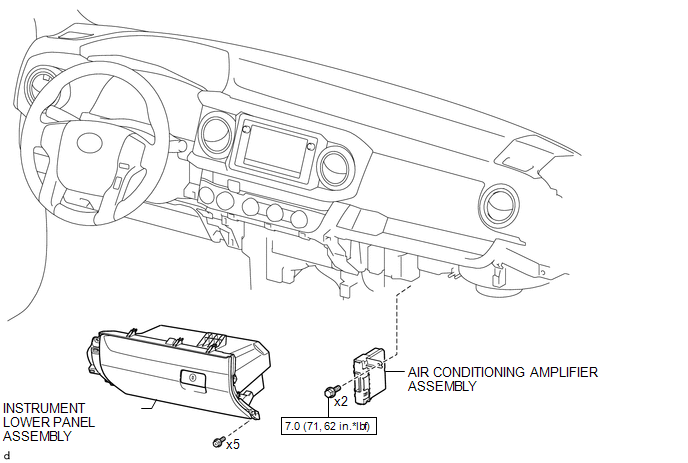
1. INSTALL AIR CONDITIONING AMPLIFIER ASSEMBLY
(a) Install the air conditioner amplifier assembly with the 2 bolts.
Torque:
7.0 N·m {71 kgf·cm, 62 in·lbf}
(b) Connect the 2 connectors.
2. INSTALL INSTRUMENT LOWER PANEL ASSEMBLY
.gif)
3. INSTALL LOWER NO. 2 INSTRUMENT PANEL AIRBAG ASSEMBLY
(See page )
Removal
REMOVAL
PROCEDURE
1. REMOVE LOWER NO. 2 INSTRUMENT PANEL AIRBAG ASSEMBLY
(See page .gif) )
)
2. REMOVE INSTRUMENT LOWER PANEL ASSEMBLY
3. REMOVE AIR CONDITIONING AMPLIFIER ASSEMBLY
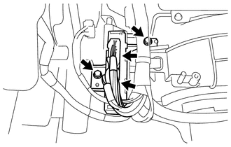
(a) Disconnect the 2 connectors.
(b) Remove the 2 bolts and air conditioning amplifier assembly.
 Air Conditioning
...

Other materials:
Adjusting the position of the air outlets
Center outlets
Direct air flow to the left or right, up or down.
Right and left side outlets
Direct air flow to the left or right, up or down.
Opening and closing the air outlets
Center outlets
Open the vent.
Close the vent.
Right and left side outlets
Open the vent.
...
Fuel Tank Cap
Inspection
INSPECTION
PROCEDURE
1. INSPECT FUEL TANK CAP ASSEMBLY
(a) Check the appearance of the fuel tank cap assembly.
(1) Check that there is no deformation or damage to the fuel tank cap assembly
or fuel tank cap gasket.
*1
Fuel Tank Cap Gasket
If the ...
Slip Indicator Light does not Come ON
DESCRIPTION
Refer to Slip Indicator Light Remains ON (See page
).
WIRING DIAGRAM
Refer to Slip Indicator Light Remains ON (See page
).
CAUTION / NOTICE / HINT
NOTICE:
When replacing the skid control ECU (master cylinder solenoid), perform
calibration (See page
).
Inspe ...
