Toyota Tacoma (2015-2018) Service Manual: Installation
INSTALLATION
PROCEDURE
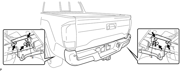
1. INSTALL REAR BUMPER ASSEMBLY
(a) Using an engine lifter or equivalent, engage the 2 pins to install the rear bumper assembly as shown in the illustration.
 Text in Illustration
|
*a |
Pin |
- |
- |
NOTICE:
- Using plate lift attachments or equivalent, set the rear bumper assembly on a flat surface.
- Be sure to perform the operation with 2 persons or more.
- Be careful not to damage the rear bumper assembly.
(b) Install the 6 bolts.
Torque:
90 N·m {918 kgf·cm, 66 ft·lbf}
(c) Connect the 3 connectors.
2. INSTALL NO. 1 RECEIVER HITCH ATTACHMENT REINFORCEMENT
(a) Engage the 4 guides and install the 2 No. 1 receiver hitch attachment reinforcements with the 8 bolts.
Torque:
90 N·m {918 kgf·cm, 66 ft·lbf}
3. PERFORM BLIND SPOT MONITOR BEAM AXIS INSPECTION (w/ Blind Spot Monitor)
Click here .gif)
4. PERFORM DIAGNOSTIC SYSTEM CHECK (w/ Blind Spot Monitor)
Click here
 Reassembly
REASSEMBLY
PROCEDURE
1. INSTALL REAR BUMPER SIDE STAY LH
(a) Install the rear bumper side stay LH with the 2 bolts.
Torque:
30 N·m {306 kgf·cm, 22 ft·lbf}
...

Other materials:
Components
COMPONENTS
ILLUSTRATION
*1
LOWER NO. 2 STEERING WHEEL COVER
*2
LOWER NO. 3 STEERING WHEEL COVER
*3
STEERING PAD
-
-
N*m (kgf*cm, ft.*lbf): Specified torque
-
...
System Diagram
SYSTEM DIAGRAM
Communication Table
Sender
Receiver
Signal
Line
Millimeter Wave Radar Sensor Assembly
Forward Recognition Camera
Pre-collision alarm signal
Pre-collision braking operation signal
...
Lost Communication with ECM / PCM "A" (U0100,U0125,U0126,U0129)
DESCRIPTION
The millimeter wave radar sensor assembly and ECM communicate with each sensor
and ECU via CAN communication.
If any malfunction is detected in a CAN communication circuit, one or more CAN
communication system DTCs are stored.
DTC No.
Detection Item
...
