Toyota Tacoma (2015-2018) Service Manual: Theft Deterrent System Communication Line High Fixation (B279A,B279A12)
DESCRIPTION
If the communication line (EFIO-IMI) to the transponder key ECU assembly is stuck high (e.g. shorted to +B), the ECM stores this DTC.
|
DTC No. |
DTC Detection Condition |
Trouble Area |
DTC Output Confirmation Operation |
|---|---|---|---|
|
B279A*1 |
Communication line (EFIO-IMI) between the ECM and transponder key ECU assembly is stuck high. |
|
Turn the ignition switch to ON and wait 6 seconds. |
|
B279A12*2 |
Communication line (EFIO-IMI) between the ECM and transponder key ECU assembly is stuck high. |
|
Turn the ignition switch to ON and wait 6 seconds. |
- *1: for 2TR-FE
- *2: for 2GR-FKS
|
Vehicle Condition when Malfunction Detected |
Fail-safe Operation when Malfunction Detected |
|---|---|
|
Engine cannot be started (initial ignition occurs and engine cranks, then ignition stops) |
Engine cannot be started |
|
DTC No. |
Data List and Active Test |
|---|---|
|
B279A*1 |
- |
|
B279A12*1 |
- |
- *1: for 2TR-FE
- *2: for 2GR-FKS
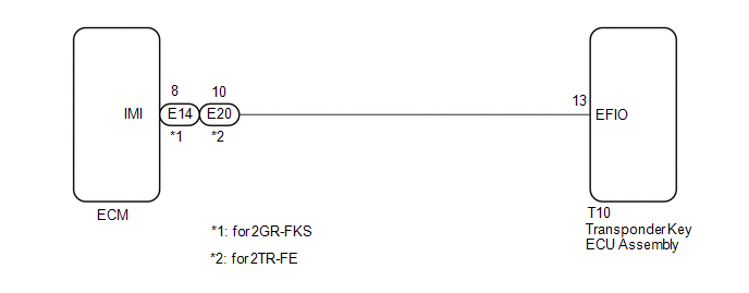
WIRING DIAGRAM
CAUTION / NOTICE / HINT
NOTICE:
- If the transponder key ECU assembly or ECM is replaced, refer to Registration
(See page
.gif) ).
). - After repair, confirm that no DTCs are output by performing "DTC Output Confirmation Operation".
PROCEDURE
|
1. |
CLEAR DTC |
(a) Clear the DTCs (See page ).
|
.gif)
|
2. |
CHECK DTC OUTPUT |
(a) Perform "DTC Output Confirmation Operation" procedure.
(b) Check for DTCs (See page ).
|
Result |
Proceed to |
|---|---|
|
DTC B279A (for 2TR-FE) or B279A12 (for 2GR-FKS) is output |
A |
|
DTC B279A (for 2TR-FE) or B279A12 (for 2GR-FKS) is not output |
B |
| B | .gif) |
USE SIMULATION METHOD TO CHECK |
|
|
3. |
CHECK CONNECTION OF CONNECTOR |
(a) Check that the connectors are properly connected to the ECM and transponder key ECU assembly.
OK:
Connectors are properly connected.
| NG | |
CONNECT CONNECTORS PROPERLY |
|
|
4. |
CHECK HARNESS AND CONNECTOR (TRANSPONDER KEY ECU ASSEMBLY - ECM) |
(a) Disconnect the T10 transponder key ECU assembly connector.
(b) Disconnect the E14*1 or E20*2 ECM connector.
- *1: for 2GR-FKS
- *2: for 2TR-FE
(c) Measure the resistance according to the value(s) in the table below.
Standard Resistance:
|
Tester Connection |
Condition |
Specified Condition |
|---|---|---|
|
T10-13 (EFIO) - E14-8 (IMI)*1 |
Always |
Below 1 Ω |
|
T10-13 (EFIO) or E14-8 (IMI) - Body ground*1 |
Always |
10 kΩ or higher |
|
T10-13 (EFIO) - E20-10 (IMI)*2 |
Always |
Below 1 Ω |
|
T10-13 (EFIO) or E20-10 (IMI) - Body ground*2 |
Always |
10 kΩ or higher |
- *1: for 2GR-FKS
- *2: for 2TR-FE
| NG | |
REPAIR OR REPLACE HARNESS OR CONNECTOR |
|
|
5. |
REPLACE TRANSPONDER KEY ECU ASSEMBLY |
(a) Replace the transponder key ECU assembly with a new one (See page
).
|
|
6. |
CLEAR DTC |
(a) Clear the DTCs (See page ).
|
|
7. |
CHECK FOR DTC |
(a) Perform "DTC Output Confirmation Operation" procedure.
(b) Check for DTCs (See page ).
|
Result |
Proceed to |
|---|---|
|
DTC B279A (for 2TR-FE) or B279A12 (for 2GR-FKS) is not output |
A |
|
DTC B279A is output (for 2TR-FE) |
B |
|
DTC B279A12 is output (for 2GR-FKS) |
C |
| A | |
END (TRANSPONDER KEY ECU ASSEMBLY WAS DEFECTIVE) |
| B | |
REPLACE ECM |
| C | |
REPLACE ECM |
 Diagnostic Trouble Code Chart
DIAGNOSTIC TROUBLE CODE CHART
HINT:
If a trouble code is stored during the DTC check, inspect the trouble areas listed
for that code. For details of the code, refer to "See page" below.
...
 Theft Deterrent System Presence Detection (B279C,B279C95)
DESCRIPTION
If an ECM that is incompatible with the engine immobiliser system is installed,
the ECM stores this DTC.
DTC No.
DTC Detection Condition
Trouble Area
...
Other materials:
Terminals Of Ecu
TERMINALS OF ECU
1. RADIO AND DISPLAY RECEIVER ASSEMBLY
Terminal No. (Symbol)
Wiring Color
Terminal Description
Condition
Specified Condition
R30-1 (FR+) - R30-7 (GND1)
LA-R - W-B
Sound signal (Front Ri ...
Voltage Inverter
Components
COMPONENTS
ILLUSTRATION
Inspection
INSPECTION
PROCEDURE
1. INSPECT VOLTAGE INVERTER ASSEMBLY
(a) Check the voltage inverter assembly.
(1) Measure the voltage according to the value(s) in the table below.
Text in Illustration
*a
Component with harness ...
Voice Recognition Microphone Disconnected (B1579)
DESCRIPTION
The radio and display receiver assembly and telephone microphone assembly are
connected to each other using the microphone connection detection signal lines.
This DTC is stored when a microphone connection detection signal line is disconnected.
DTC Code
DTC Det ...
