Toyota Tacoma (2015-2018) Service Manual: Terminals Of Ecm
TERMINALS OF ECM
HINT:
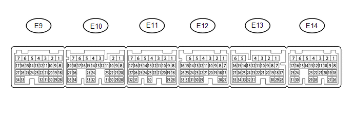
The standard normal voltage between each pair of ECM terminals is shown in the table below. The appropriate conditions for checking each pair of terminals are also indicated. The result of checks should be compared with the standard normal voltage for that pair of terminals, displayed in the Specified Condition column. The illustration above can be used as a reference to identify the ECM terminal locations.
|
Terminal No. (Symbol) |
Wiring Color |
Terminal Description |
Condition |
Specified Condition |
|---|---|---|---|---|
|
E14-2 (BATT) - E11-1 (E1) |
L - W-B |
Battery (for measuring battery voltage and for ECM memory) |
Always |
11 to 14 V |
|
E12-6 (+BM) - E11-1 (E1) |
GR - W-B |
Power source of throttle actuator |
Always |
11 to 14 V |
|
E14-3 (+B) - E11-1 (E1) |
B - W-B |
Power source of ECM |
Ignition switch ON |
11 to 14 V |
|
E14-4 (+B2) - E11-1 (E1) |
B - W-B |
Power source of ECM |
Ignition switch ON |
11 to 14 V |
|
E14-25 (MREL) - E11-1 (E1) |
GR - W-B |
EFI-MAIN NO. 1 relay operation signal |
Ignition switch ON |
11 to 14 V |
|
E9-26 (VCNE) - E11-1 (E1) |
R - W-B |
Power source of crankshaft position sensor (specific voltage) |
Ignition switch ON |
4.5 to 5.5 V |
|
E9-25 (NE+) - E9-33 (NE-) |
B - G |
Crankshaft position sensor |
Idling |
Pulse generation |
|
E13-24 (SPD) - E11-1 (E1) |
R - W-B |
Vehicle speed signal from combination meter assembly |
Driving at 20 km/h (12 mph) |
Pulse generation |
|
E11-1 (E1) - Body ground |
W-B - Body ground |
Ground circuit of ECM |
Always |
Below 1 Ω |
 Diagnosis System
DIAGNOSIS SYSTEM
1. DESCRIPTION
(a) To check DTCs, connect the Techstream to the Data Link Connector 3 (DLC3)
of the vehicle. The Techstream displays DTCs and freeze frame data. The DTCs and
fre ...
 Check Mode Procedure
CHECK MODE PROCEDURE
1. DESCRIPTION
Check mode has a higher sensitivity to malfunctions and can detect malfunctions
that cannot be detected in normal mode. Check mode can also detect all of the ma ...
Other materials:
System Description
SYSTEM DESCRIPTION
1. WIRELESS DOOR LOCK CONTROL SYSTEM
The wireless door lock control system functions to lock and unlock all the doors
from a distance. The system is controlled by a door control transmitter module set
sub-assembly which sends radio waves to the door control receiver. The mai ...
AVC-LAN Circuit
DESCRIPTION
Each unit of the navigation system connected to the AVC-LAN (communication bus)
transfers the switch signals using the AVC-LAN.
If a short to +B or short to ground occurs in the AVC-LAN, the navigation system
will not function normally because communication is not possible.
WIRING ...
ECM Communication Circuit Malfunction (C1203)
DESCRIPTION
The circuit sends TRAC, A-TRAC and VSC control information from the skid control
ECU (master cylinder solenoid) to the ECM, and engine control information from the
ECM to the skid control ECU (master cylinder solenoid) via the CAN communication
system.
DTC Code
...
