Toyota Tacoma (2015-2018) Service Manual: Entire Combination Meter does not Operate
DESCRIPTION
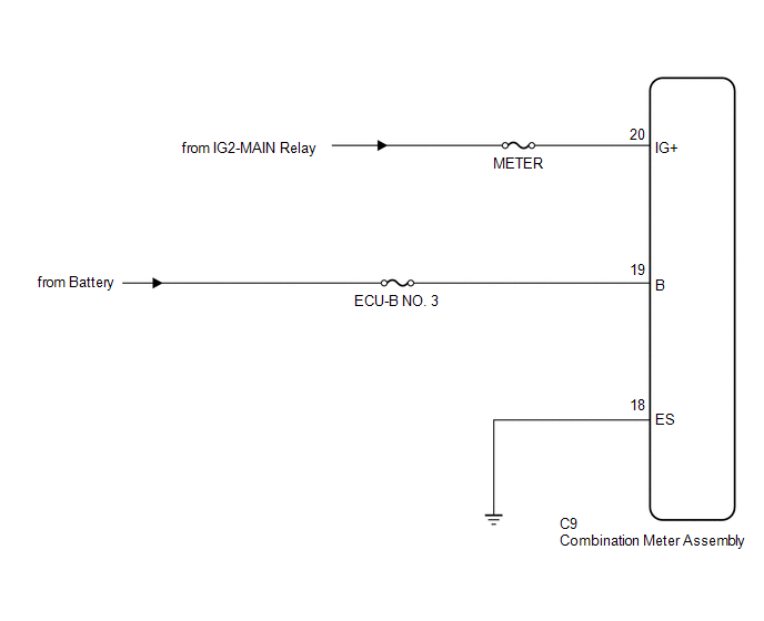
This circuit is the power source circuit for the meter. This circuit provides two types of power sources, one is a constant power source mainly used as a backup power source, and the other is an IG power source mainly used for signal transmission. The constant power source is mainly used as a backup power source for the meter CPU, however, it is also used for CAN communication. If a voltage of 12 V is not applied to terminal IG+ when turning the ignition switch ON, the indicators will not operate.
WIRING DIAGRAM
CAUTION / NOTICE / HINT
CAUTION:
Inspect the fuses for circuits related to this system before performing the following inspection procedure.
PROCEDURE
|
1. |
CHECK HARNESS AND CONNECTOR (COMBINATION METER ASSEMBLY - BATTERY AND BODY GROUND) |
|
(a) Disconnect the combination meter assembly connector. |
|
(b) Measure the voltage according to the value(s) in the table below.
Standard Voltage:
|
Tester Connection |
Switch Condition |
Specified Condition |
|---|---|---|
|
C9-20 (IG+) - Body ground |
Ignition switch ON |
11 to 14 V |
|
C9-19 (B) - Body ground |
Always |
11 to 14 V |
(c) Measure the resistance according to the value(s) in the table below.
Standard Resistance:
|
Tester Connection |
Condition |
Specified Condition |
|---|---|---|
|
C9-18 (ES) - Body ground |
Always |
Below 1 Ω |
|
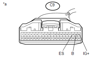
*a |
Front view of wire harness connector (to Combination Meter Assembly) |
| OK | .gif) |
REPLACE COMBINATION METER ASSEMBLY |
| NG | |
REPAIR OR REPLACE HARNESS OR CONNECTOR |
 Lost Communication with ECM / PCM "A" (U0100,U0129,U0142,U0151,U0163,U023A,U1104)
DESCRIPTION
The combination meter communicates with the ECM, skid control ECU, power steering
ECU, main body ECU (multiplex network body ECU), airbag sensor assembly, navigation
receiver assembly ...
 Speedometer Malfunction
DESCRIPTION
The meter CPU receives vehicle speed signals from the skid control ECU via the
CAN communication system (CAN V1 Bus). The speed sensor detects the wheel speed
and sends the appropriat ...
Other materials:
System Description
SYSTEM DESCRIPTION
1. GENERAL
(a) This system uses ultrasonic sensors to detect any obstacles at the corners
and the rear of the vehicle. The system then informs the driver of the distance
between the sensors and an obstacle as well as their positions by indicating them
on the multi-informat ...
Rear Seat Inner Belt Assembly(for Access Cab)
Components
COMPONENTS
ILLUSTRATION
Removal
REMOVAL
PROCEDURE
1. REMOVE REAR NO. 1 SEAT INNER BELT ASSEMBLY
(a) Open the 2 anchor covers.
(b) Loosen the 2 bolts to remove the 2 rear No. 1 seat inner belt assemblies.
Installation
I ...
Terminals Of Ecu
TERMINALS OF ECU
1. AIR CONDITIONING AMPLIFIER ASSEMBLY
HINT:
Check from the rear of the connector while it is connected to the air conditioning
amplifier assembly.
Terminal No.
(Symbol)
Wiring Color
Terminal Description
Condition
Spe ...
